Hollow cathode central axial powder-feeding plasma spraying gun

A technology of axial powder feeding and hollow cathode, which is applied in the direction of plasma welding equipment, arc spraying, spraying devices, etc., can solve the problems of arc voltage fluctuation, arc heating efficiency reduction, particle state parameter dispersion, etc. Good stability, the effect of improving stability

Inactive Publication Date: 2003-10-15
XI AN JIAOTONG UNIV
View PDF0 Cites 15 Cited by
  • Summary
  • Abstract
  • Description
  • Claims
  • Application Information

AI Technical Summary

Problems solved by technology

[0003] The traditional plasma coating guns adopt the powder feeding method outside the gun (referred to as the powder feeding method) or the powder feeding method inside the gun through the anode nozzle (referred to as the powder feeding method). Due to the joint influence of powder gas flow rate, powder particle size distribution and powder material density, as well as the temperature gradient and velocity gradient of the plasma jet, the trajectory of the particles diverges and it is difficult to fully enter the high temperature region of the plasma jet, and the dispersion of the particle trajectory makes the particles flow in different directions The state of the collision with the matrix increases the inhomogeneity of the coating structure and performance, especially when the spraying material is two or more mixed powders with different densities, the problem of particle state parameter dispersion is more serious, which will lead to the coating performance Serious non-uniformity occurs, and it is difficult for traditional plasma spray guns to effectively solve this problem
[0004] The more common method is to make up for the uneven heating and acceleration of particles by increasing the arc power, but the increase in plasma arc power also brings other problems, such as the reduction in the heating efficiency of the arc (the heat used to heat the powder only accounts for the arc 3% to 5% of the heat), when spraying smaller parts, the larger diameter of the plasma jet deposition beam spot leads to lower powder deposition efficiency, etc.
[0005] In order to improve the heating efficiency of the powder and improve the uniformity of the coating performance, a high-power plasma spray gun with axial powder feeding mode appeared in the 1990s, and its structure mostly adopts a multi-electrode structure, such as a three-cathode structure spray gun and a multi-pair electrode structure spray gun. , under this structure, the powder can be fed from the axis of the spray gun, as a result, the uniformity of heating acceleration of the particles and the efficiency of powder deposition are improved, but the structure of the spray gun is complicated and the equipment cost is high
However, the method of processing the powder feeding channel at the center of the solid cathode has the following problems: first, the cathode is always in a high temperature state during the spraying process, and the powder is easy to melt near the end of the cathode to block the powder feeding channel, especially for metals with a low melting point Therefore, continuous spraying cannot be achieved. Secondly, the powder feeding airflow in the center hole directly enters the arc, causing disturbance to the arc, resulting in fluctuations in arc voltage and poor stability, making it difficult to meet the requirements of spraying.

Method used


Image

  • Hollow cathode central axial powder-feeding plasma spraying gun
  • Hollow cathode central axial powder-feeding plasma spraying gun
  • Hollow cathode central axial powder-feeding plasma spraying gun

Examples


Embodiment 1

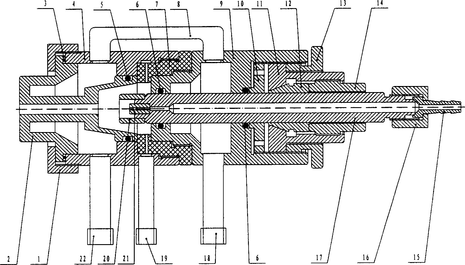
[0045] see figure 1 , 5 6. According to the technical solution of the present invention, the central axial powder feeding plasma spray gun includes: gland 1, anode nozzle 2, sealing ring 3, front gun body 4, sealing ring 5, sealing ring 6, insulator 7, cooling water pipe 8, rear Gun body 9, sealing ring compression nut 10, adjustment nut 11, elastic collet 12, compression nut 13, lock nut 14, powder feeding pipe joint 15, nut 16, cathode rod 17, cathode water and electricity connector 18, inlet Gas pipe connector 19, outer tungsten tube 20, inner tube 21, anode water and electricity connector 22.

[0046] The front gun body, the rear gun body, the insulator and the sealing ring are mechanically connected; the sealing ring 3 and the anode nozzle 2 are sequentially installed through the gland 1 at one end of the front gun body 4 by mechanical means.

[0047]One end of the cathode rod 17 close to the anode nozzle 2 is concentrically arranged with an inner tube 21 and an outer ...

Embodiment 2

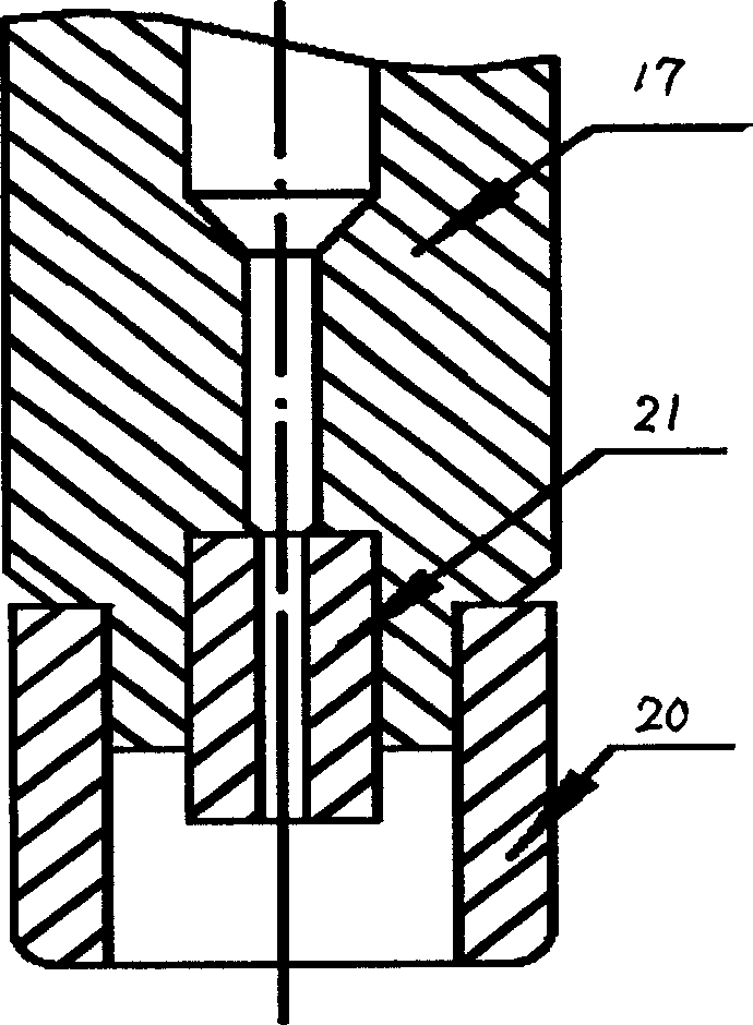
[0061] see figure 2 . According to the technical scheme of the present invention, such as figure 1 The hollow cathode structure of the plasma spraying gun shown includes a hollow support body of the cathode, and an inner tube with a through hole and an outer tungsten tube are also arranged at one end of the cathode hollow support body, and the inner tube is arranged on the hollow support body of the cathode. On the through hole, the outer tungsten tube is arranged on the outer diameter of one end of the cathode hollow support body, and there is a certain gap between the two tungsten tubes. Copper is used as the supporting body, the inner tube and the outer tungsten tube are connected at one end of the supporting body, and the material of the tungsten tube is cerium-tungsten alloy.

Embodiment 3

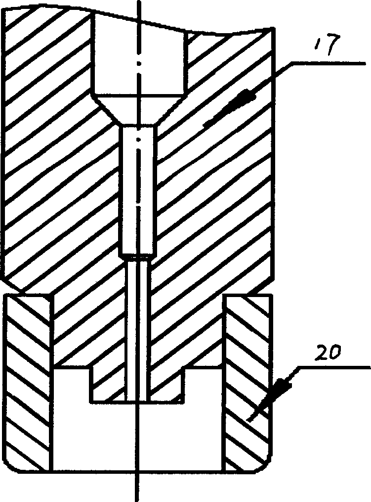
[0063] see image 3 . According to the technical scheme of the present invention, such as image 3 As shown, the inner tube and the cathode hollow support body are made of red copper at the same time, and the two are combined into one to form a whole. The solution of this kind of embodiment is relatively simple.


PUM

PropertyMeasurementUnit
diameteraaaaaaaaaa
thicknessaaaaaaaaaa
thicknessaaaaaaaaaa

Abstract

The present invention is one plasma spray gun with hollow cathode and powder feeding in central axle direction. The hollow cathode is made of concentric inner tube and outer tungsten tube, and the anode has nozzle cavity with trapezoidal cross section. The plasma spray gun in such a structure can control effectively the flying locus of powder inside the plasma jet and feed powder to the center of the plasma jet to heat and accelerate sprayed particles effectively, and has stable arc burning, less adhesion of powder and long service life of the electrodes.

Description

1. Technical field [0001] The invention relates to a structure of a plasma spraying gun mainly used in the field of machinery and electric appliance manufacturing, in particular to a plasma spraying gun with hollow cathode central axial feeding powder. 2. Background technology [0002] Plasma spraying uses the non-transferred plasma arc generated by the plasma spray gun as the heat source. When the working gas passes through the nozzle hole, it is heated to a very high temperature by the arc, and it expands violently and sprays out rapidly, forming a high-temperature and high-speed plasma jet. The sprayed material is in the form of powder The form is sent to the plasma jet, where it is heated and accelerated to form a molten particle flow, which hits the surface of the substrate at high speed to form a coating. [0003] The traditional plasma coating guns adopt the powder feeding method outside the gun (referred to as the powder feeding method) or the powder feeding method i...

Claims


Application Information

Patent Timeline
Patent Type & Authority Applications(China)
IPC IPC(8): B05B5/06B05B7/16B23K10/00
Inventor 李长久孙波王豫跃杨冠军
Owner XI AN JIAOTONG UNIV
Why Eureka
Try Eureka