

Optical circuit element and method of producing the same
A component and optical path technology, applied in the field of optical path components, optical path components and the production of the components, can solve the problems of becoming expensive, complicated processing steps, expensive cutting of multi-layer dielectric films, etc.
- Summary
- Abstract
- Description
- Claims
- Application Information
AI Technical Summary
Problems solved by technology
Method used
Image

Examples
example 1
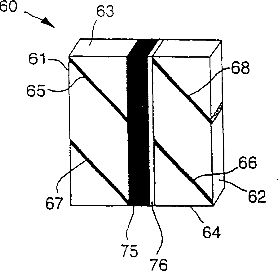
[0076] figure 2 A preferred example of a four-terminal optical circulator is shown according to the present invention. The illustrated optical circulator 10 has four ports, that is, a first optical input / output port 1, a second optical input / output port 2, a third optical input / output port 3, and a fourth optical input / output port 4. Although not shown, the light input / output port is a parallel beam system composed of aspheric lenses and optical fibers. As shown in the figure, the optical circulator is composed of the following: two polarized light separation elements 5 and 6 composed of multilayer polymer films, total reflection mirrors 7 and 8 composed of multilayer films, and a polarization plane rotation independent of the direction of light propagation An element 15 (first polarization plane rotating element), a polarization plane rotating element 16 (second polarization plane rotating element) dependent on the light propagation direction, and means for applying a magn...
example 2
[0086] Figure 7 Another preferred embodiment of a four-terminal optical circulator is shown according to the present invention. From the perspective of the arrangement and operation of the optical components, the illustrated optical circulator 10 uses a Faraday rotator composed of a magnetized garnet having a square hysteresis curve instead of the bismuth-substituted magnetized garnet (GdBiFe garnet) used in Example 1. ) is the same as the optical circulator described in Example 1 above, except that the polarization plane rotation element 25 (the first polarization plane rotation element) is independent of the light propagation direction. The magnetic garnet with a square hysteresis curve used here is the Bi-generation rare earth iron garnet Eu 0.9 Ho 1.1 Bi 1.0 Fe 4.2 Ga 0.8 0 12 , its thickness is about 0.1mm, and once it is magnetized by an external magnetic field, it can maintain a magnetization of about 350 Oersted even if no external magnetic field is applied.
...
example 3
[0089] Figure 8 shows an example used as an optical switch, it refers to the figure 2 The four-terminal optical circulator of the present invention described in. In the illustrated example, a yoke 24 wound with a coil 23 and made of a semi-hard magnetic material is used as a device for applying a magnetic field, and a DC source 21 connected to the coil 23 through a switch 22 is used as a device for providing a magnetic field. current device. When the optical circulator 10 is placed in the central space of the ring yoke 24 and when the current device changes the direction of the applied current, the magnetization of the polarization plane rotating element can be reversed regardless of the propagation direction of light in the optical circulator. Therefore, the optical circulator 10 can operate as a four-terminal (2:2) optical switch. As a modified example, a 2:2 optical switch can be operated as a 1:2 optical switch. In this optical switch, placing the mechanism for drivi...
PUM
| Property | Measurement | Unit |
|---|---|---|
| thickness | aaaaa | aaaaa |
| diameter | aaaaa | aaaaa |
| thickness | aaaaa | aaaaa |
Abstract
Description
Claims
Application Information