Blast mechanism

A blower, centrifugal blower technology, applied in the direction of mechanical equipment, engine components, combustion engines, etc., can solve the problems of high load, affecting cooling efficiency, reducing the economy of working instruments, etc., and achieve the effect of reducing flow loss

Inactive Publication Date: 2004-05-19
ANDREAS STIHL AG & CO KG
View PDF0 Cites 4 Cited by
  • Summary
  • Abstract
  • Description
  • Claims
  • Application Information

AI Technical Summary

Problems solved by technology

The dust particles that are carried out through the exhaust port and fed into the gasifier together with the combustion air flow will cause a high load on the air filter connected in front of the gasifier, which will cause frequent filter replacement and reduce this. Economical operation of working instruments
The placement of the discharge outlet and the pre-separator in the blower can also adversely affect the delivered cooling air flow, thereby affecting the desired cooling efficiency
Furthermore, the achievable pressure values ​​in the combustion gas stream are not always satisfactory

Method used


Image

  • Blast mechanism
  • Blast mechanism
  • Blast mechanism

Examples


Embodiment Construction

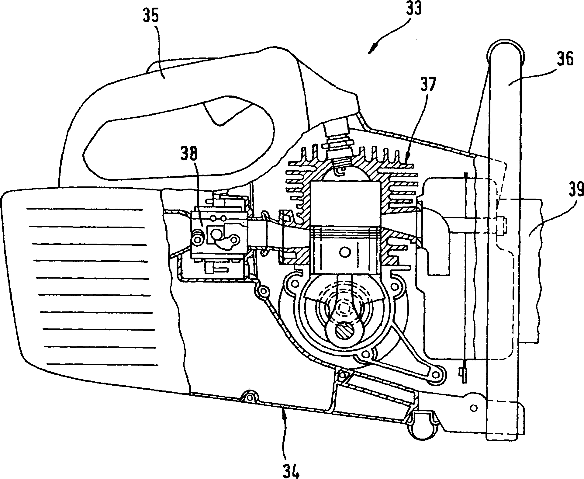
[0022] figure 1 A partial cross-sectional view of a working instrument 33 is shown. The working instrument includes a housing 34 with an internal combustion engine 37 inside and a tool 39 driven by the internal combustion engine. An upper handle 35 and a front handle 36 are provided on the housing. In front of the internal combustion engine 37 is a vaporizer.

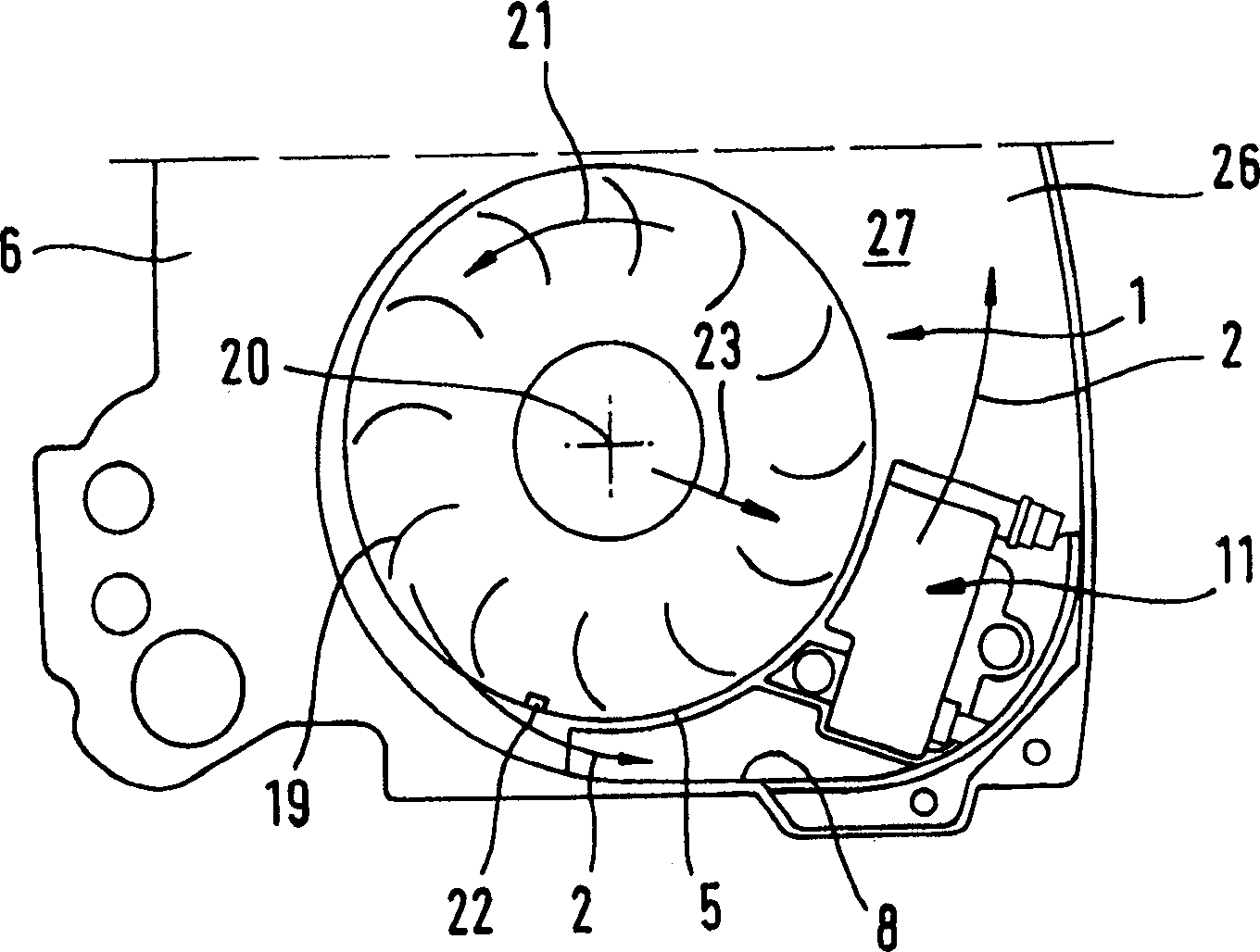
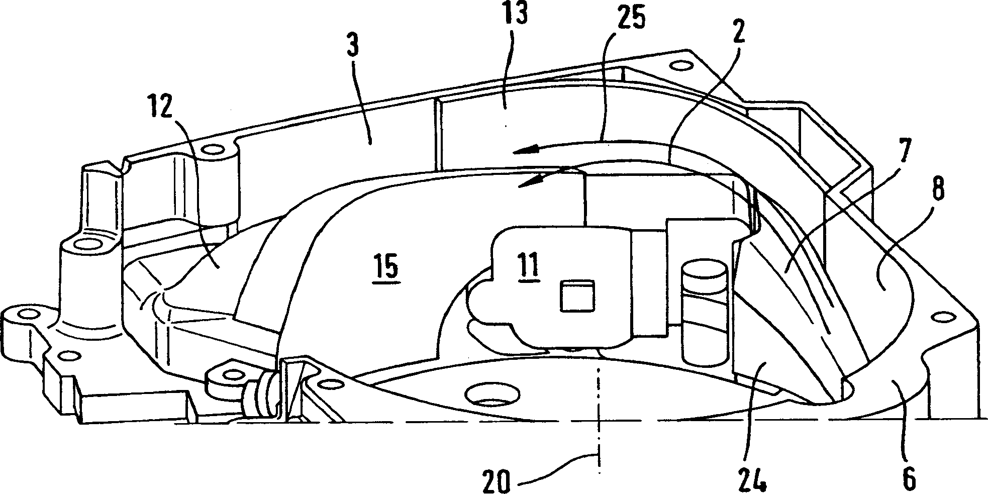
[0023] figure 2 A schematic diagram of the main components of a centrifugal blower 1 is shown. The centrifugal blower includes a blower wheel 5 and a spiral blower housing 6 that at least partially surrounds the blower wheel 5. For the sake of clarity, only an open half shell is shown for the blower housing 6, which constitutes an end wall 27 located in the plane of the blower wheel 5 and a spiral shape located radially outside of the blower wheel 5. Expanded peripheral wall 8.

[0024] The blower wheel 5 has a plurality of blades 19 and is rotatably supported around a rotating shaft 20. Through the rotation of the blow...


PUM


Abstract

A fan arrangement of a portable handheld work apparatus is driven by an internal combustion engine and includes a radial fan (1) which includes a fan wheel (5) and a spirally-shaped fan housing (6) which encloses the fan wheel (5) at least partially. A take-out opening (3) is provided in the radial fan (1) in the region of the moved air flow (2) for diverting a combustion air flow (4) for the engine. The combustion air flow (4) is branched off from the air flow (2). In the radial direction outside of the fan wheel (5), there is an aerodynamically formed guide ramp (7) provided in the air flow (2) which rises in the axial direction. The take-out opening (3) is arranged downstream of the guide ramp (7).

Description

Technical field [0001] The present invention relates to a blower mechanism having the features described in the preamble of claim 1 for a manual working instrument driven by an internal combustion engine. Background technique [0002] Known embodiments of manual working instruments driven by internal combustion engines, such as chainsaws, free slicers, suction / blowers, etc., have a centrifugal blower for cooling the internal combustion engine. Here, the centrifugal blower includes a blower wheel and a spiral blower housing at least partially surrounding the blower wheel. The blower is installed on the crankshaft of the internal combustion engine and rotates at the same speed as the crankshaft. Using the synchronous rotation of the blower wheel and the crankshaft, the blower wheel can also be used to control an ignition device of the internal combustion engine. To this end, an ignition coil extending into the inside of the blower housing and a co-rotating ignition magnet fixed on ...

Claims


Application Information

Patent Timeline
Patent Type & Authority Applications(China)
IPC IPC(8): F01P1/02F01P5/06F01P11/12F02B63/02F02M35/10F02P3/02
CPCY02T10/146F01P1/02F02M35/1019F02P3/02F02M35/10262F02B63/02F01P11/12F02M35/1017F01P5/06Y02T10/12
Inventor G·梅尔F·基塞维特
Owner ANDREAS STIHL AG & CO KG
Why Eureka
Try Eureka