Method for making a lead fabric battery using novel lead fabric as polar plate grid
A manufacturing method and plate technology, applied in lead-acid batteries, lead-acid battery electrodes, lead-acid battery construction, etc., can solve the problem of large internal resistance of valve-controlled sealed lead-acid battery plates and the combination of active materials and grids Insufficient strength, low weight-to-energy ratio, etc., to achieve the effects of small surface density error, high tensile strength, and advanced technology
- Summary
- Abstract
- Description
- Claims
- Application Information
AI Technical Summary
Problems solved by technology
Method used
Image
Examples
Embodiment 1
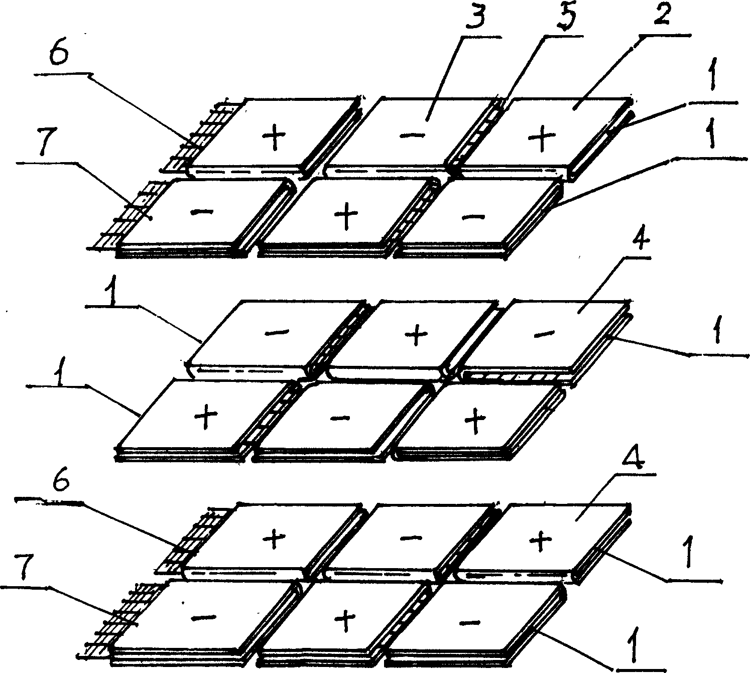
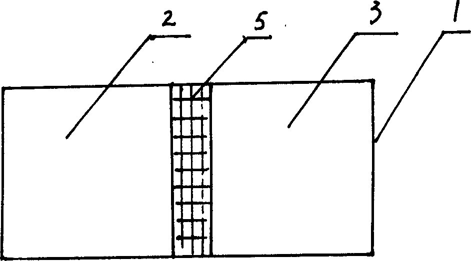
[0035] Embodiment 1: see figure 1 , figure 2 The present invention first adopts the continuous belt-shaped lead cloth material produced by the process of "physical vapor deposition-electrodeposition-heat treatment" or "conductive paint coating-electrodeposition-heat treatment", and coats positive electrode paste 2 and negative electrode lead paste on both sides of the lead cloth. Paste 3, be coated with macromolecule insulating acid-resistant coating 5 in the middle, as commercially available epoxy resin coating. Then cut into required specifications of bipolar plates and monopolar plates. In the special fixture, two bipolar plates 1 and one unipolar plate are placed on the first layer, and three bipolar plates are placed on the second layer, or each bipolar plate or unipolar plate is separated by ultrafine glass fiber The board is AGM wrapped, and so on, and the number of stacked layers depends on the battery capacity to be assembled. AGM partitions 4 are placed between l...
Embodiment 2
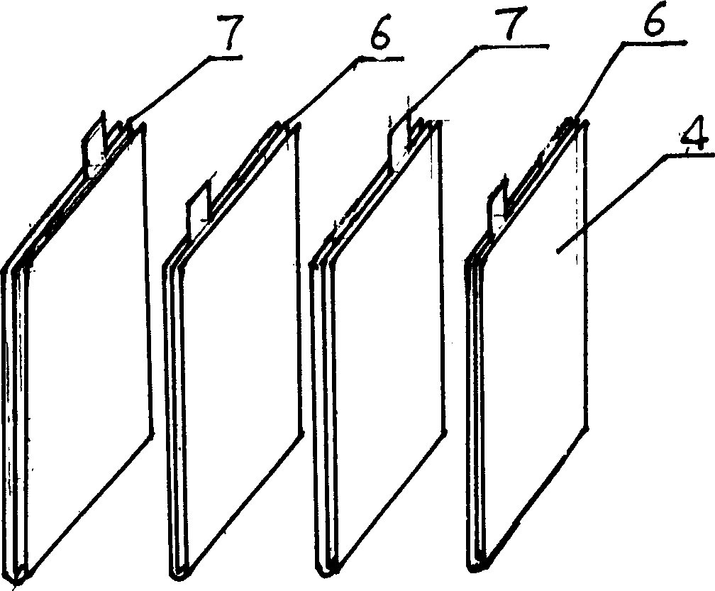
[0036] Example 2: see image 3 , Figure 4 , the continuous strip-shaped lead cloth material produced by "physical vapor deposition-electrodeposition-heat treatment" or "conductive paint coating-electrodeposition-heat treatment" technology, cut into the required size grid, and coated on both sides respectively Cover positive electrode paste or negative electrode paste to form positive electrode plate 6 or negative electrode plate 7, put a positive electrode on the special fixture, put a separator 4 on it, then put a negative electrode, and put a separator or positive electrode plate on the negative electrode 1. The negative plate is wrapped with ultra-fine glass fiber separator AGM, and so on. The number of plates depends on the capacity of the assembled battery, and then the frame is used to fix the pole group. The ends of the positive and negative electrodes are welded together with bus bars, vertically or horizontally. Put it in the battery slot.
Embodiment 3
[0037] Embodiment 3: see Figure 5 , Figure 6 , using the "physical vapor deposition-electrodeposition-heat treatment" or "conductive paint coating-electrodeposition-heat treatment" process technology to produce continuous strip-shaped lead cloth materials, cut into long strip grids of required specifications, and place them on the positive and negative electrodes Use the different positions of the grid to weld the lead pole pieces 8 by roll welding, then apply positive lead paste and negative lead paste respectively to make positive plate 6 and negative plate 7, and the active material is coated on both sides of the grid. On the special jig, put an AGM separator 4 slightly wider than the pole plate, then put the positive electrode, then put an AGM separator, and finally put the negative electrode, wind them together and put them into the battery tank 9, and roll the positive and negative electrodes. The protruding parts of the pole pieces are welded together with bus bars 1...
PUM
 Abstract
Description
Claims
Application Information
 - R&D
- Intellectual Property
- Life Sciences
- Materials
- Tech Scout
- Unparalleled Data Quality
- Higher Quality Content
- 60% Fewer Hallucinations
Browse by: Latest US Patents, China's latest patents, Technical Efficacy Thesaurus, Application Domain, Technology Topic, Popular Technical Reports.
© 2025 PatSnap. All rights reserved.Legal|Privacy policy|Modern Slavery Act Transparency Statement|Sitemap|About US| Contact US: help@patsnap.com


