Three-level LLC series resonance DC/DC transformer

A series resonance and three-level technology, which is applied in the direction of adjusting electrical variables, high-efficiency power electronic conversion, and conversion equipment with intermediate conversion to AC, can solve the problems of performance degradation and high price, and achieve reduced voltage stress and large input and output Effect of voltage regulation range

Inactive Publication Date: 2004-08-25
ZHEJIANG UNIV
View PDF1 Cites 38 Cited by
  • Summary
  • Abstract
  • Description
  • Claims
  • Application Information

AI Technical Summary

Problems solved by technology

For MOSFET devices suitable for high-frequency power supplies, products of thi...

Method used


Image

  • Three-level LLC series resonance DC/DC transformer
  • Three-level LLC series resonance DC/DC transformer
  • Three-level LLC series resonance DC/DC transformer

Examples


Embodiment Construction

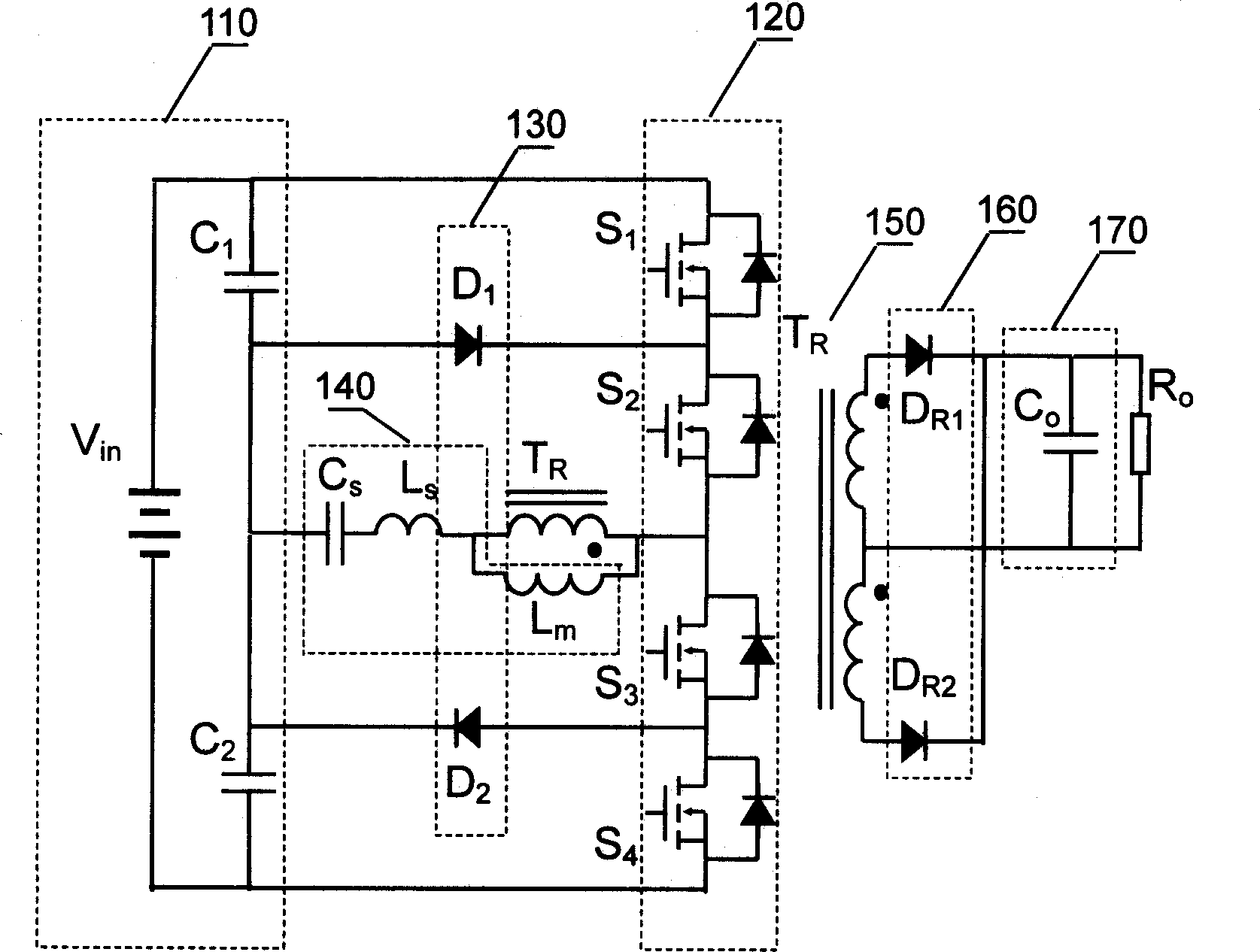
[0027] figure 2 Shown is a specific circuit diagram of the three-level LLC series resonant DC / DC converter of the present invention. The converter includes a voltage dividing capacitor 110, an inverter 120, a clamping circuit 130, a resonance circuit 140, and an isolation transformer T R , rectifier circuit 160 , filter circuit 170 . In the illustration, the voltage dividing capacitor 110 consists of two capacitors C connected in series 1 , C 2 composition to generate two voltage sources that are only half the input voltage. The inverter 120 is formed by connecting four switches S1 to S4 in series, and is used to generate a square wave or a staircase wave. The clamp circuit 130 consists of two diodes D 1 , D 2 composition, where the first diode D 1 Connected to the midpoint of the voltage divider capacitor and the first switch S 1 source and second switch S 2 between the junction of the drain, the second diode D 2 Connected to the midpoint of the voltage divider cap...


PUM


Abstract

This invention LLC serial resonance DC/DC converter includes a bleeder capacitor, an inverter composed of four serial switches, a resonance circuit, a clamp, an isolation transformer, a commutating circuit and a filter, capable of realizing large input/output voltage regulation sphere with small frequency variable sphere by LLC resonance circuit with dual intrinsic resonance frequency, at the same time, the switch is effectively clamped by a pair of clamp diodes, so that each switch voltage stress is half of the input voltage and ZVS is realized in all sphere without any additional circuit, the commutation diode works at the ZCS state.

Description

technical field [0001] The present invention relates to a power supply system including a DC / DC converter. More particularly, the present invention relates to an improved circuit design and construction to achieve better power conversion efficiency, wider operating range, better soft-switching performance and adaptability to high input voltages. Background technique [0002] LLC series resonant DC / DC converter disclosed in Chinese patent CN1368787A (see figure 1 The advantages of ) are: the natural zero voltage switching (ZVS) of the switch, the natural zero current switching (ZCS) of the rectifier diode, there is no reverse recovery problem, and there is no voltage spike. Can work over a wide range without appreciably affecting efficiency. The high-end input has high efficiency, which is very suitable for occasions where the power-off hold time is required. The structure is also very simple, and the entire converter only needs one magnetic elemen...

Claims


Application Information

Patent Timeline
IPC IPC(8): H02M3/28H02M3/335
CPCY02B70/1491Y02B70/10
Inventor 顾亦磊吕征宇钱照明
Owner ZHEJIANG UNIV
Why Eureka
Try Eureka