
Integrated adhesive head of sheet adhesive machine

A mounting head, integrated technology, applied in the direction of assembling printed circuits, electrical components, electrical components, etc. with electrical components, can solve the problems of increased cost, complex structure, unreasonable structure, etc., and achieves reduced assembly volume, Reasonable structure layout and the effect of improving flexibility

Inactive Publication Date: 2004-09-29
广州市羊城科技实业有限公司
View PDF0 Cites 18 Cited by
  • Summary
  • Abstract
  • Description
  • Claims
  • Application Information

AI Technical Summary

Problems solved by technology

At present, domestic equipment of this kind is mostly purchased from large multinational companies in the world. Not to mention the high price, the structure is not reasonable
From the perspective of the motion control of the placement head assembly and the placement spindle, the technologies at home and abroad can be mainly divided into three categories: one is the use of gear / rack transmission systems. Easy, but the problem is that it is difficult to improve the motion control accuracy of the mounting spindle, or the complexity of the mechanism must be increased in order to improve the transmission accuracy, which in turn causes the weight and volume of the mounting head assembly to increase greatly, which in turn will cause the placement In order to ensure the mounting accuracy and the service life of the machine, the large impact force of the mounting spindle downwards for high-speed mounting motion can only increase the size and weight of the guide rail frame that hangs the mounting head assembly and drives it to translate , resulting in a bulky and heavy machine, and a corresponding increase in cost
There is another type that is often used by large foreign high-tech companies in this regard, that is, the transmission / control system in which the servo motor under the control of digital or analog electronic equipment drives the lifting screw. This type of system uses advanced control algorithms and correspondingly accurate light , electrical and mechanical execution equipment, forming a complete control loop, high control precision, fast response, high placement efficiency, small size of the whole machine, high reliability, but the price of the whole machine under this type of technical solution is high, single It is the supporting lifting screw, which is difficult to manufacture domestically, and the price of outsourcing is very high. In addition, the complex and sophisticated software and hardware control system is not conducive to further application development by domestic users.
The third category is the drive control and transmission system using stepper motors and synchronous conveyor belts. This type of system belongs to open-loop control. The electrical control is relatively simple, and the control accuracy is not particularly high. It is reasonable to supplement the control correction of the photoelectric sensor system. To meet the requirements of high-precision control, but due to the unreasonable structure of the existing placement head assembly, the space volume of the placement head assembly is too large, causing the placement head assembly to be heavy and clumsy, which also affects the whole machine, resulting in The volume of the machine is relatively large and the structure is complex, which cannot meet the increasingly high requirements of the market.
And the above three types of control transmission systems have a common disadvantage: that is, the transmission mechanism is complex, inefficient, and some are very expensive
These shortcomings not only bring great difficulties to the user to adjust the placement machine according to the specific conditions of the parts and products to be placed, but also limit the user's ability to develop the potential of the placement machine and adapt to market changes quickly and quickly. The main restrictive bottleneck factors to improve the accuracy of placement machines

Method used


Image

  • Integrated adhesive head of sheet adhesive machine
  • Integrated adhesive head of sheet adhesive machine
  • Integrated adhesive head of sheet adhesive machine

Examples


Embodiment 1

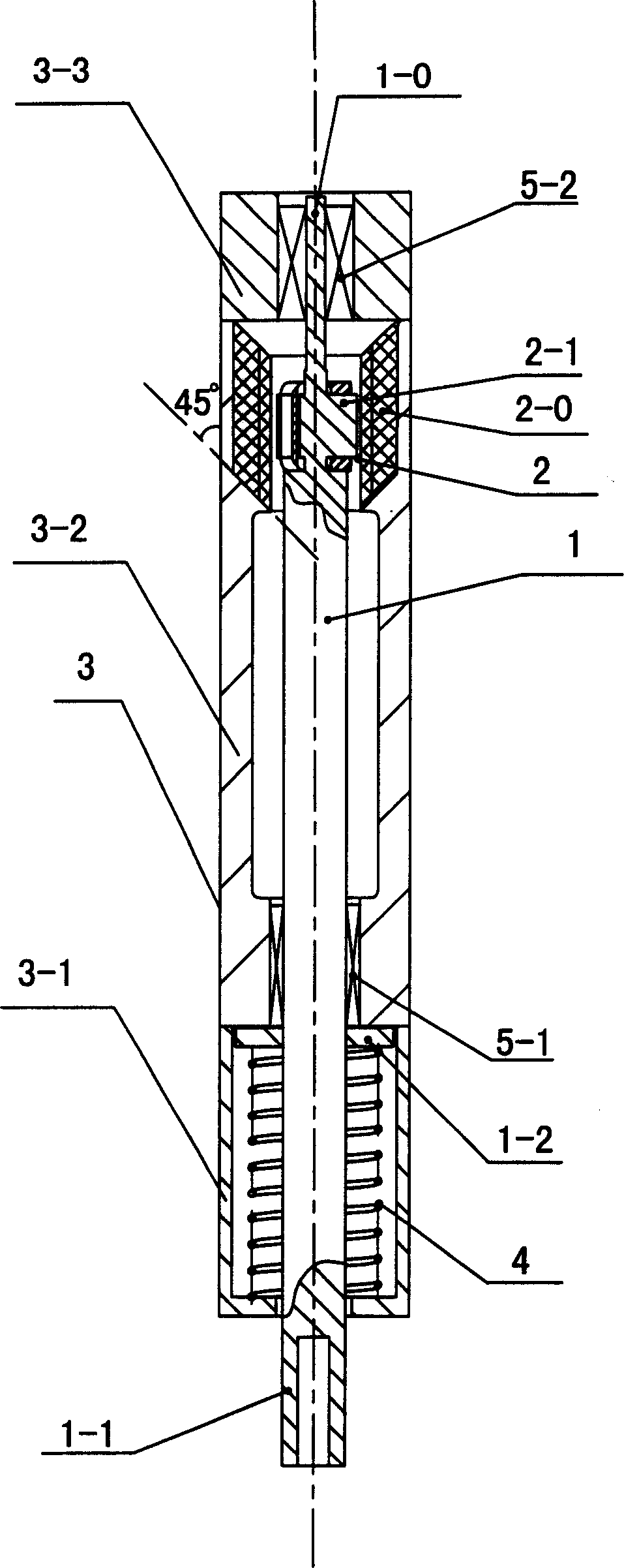
[0024] Such as figure 1 Shown: an integrated placement head of a placement machine of the present invention, the placement head includes a drive motor mounted on the placement head frame, a placement spindle and a suction nozzle, the interior of the placement head frame The main structure is the cylinder wall 3 of the upright multi-corrugated column, and the mounting spindle 1 is located on the central axis of the cylinder wall 3 of the mounting head; the driving motor 2 is a set that can simultaneously drive the mounting spindle 1. The mover 2-1 and the stator 2-0 are composed of a quantitative rotating motion and a quantitative lifting motion. The stator 2-0 of the driving motor 2 is radially symmetrical and fixed in the inner cylinder of the placement head in an axial depth. Correspondingly, on the wall 3, the mover 2-1 of the drive motor is radially symmetrical and fixedly installed on the surface of the mounting spindle 1 in the axial depth; in the axial dimension, the T...

Embodiment 2

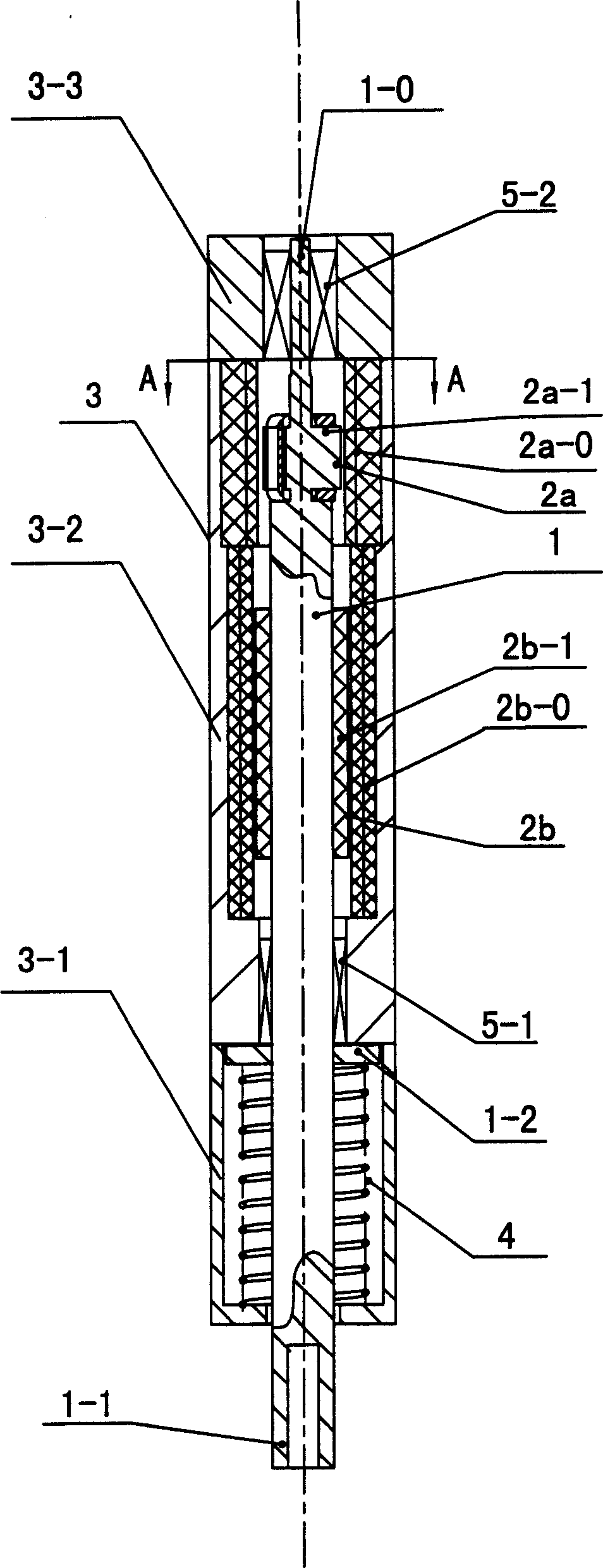
[0030] Such as figure 2Shown: an integrated mounting head of a placement machine of the present invention, the mounting head includes a drive motor mounted on the frame of the mounting head, a mounting spindle and a suction nozzle, and the drive motor is respectively composed of two Set of movers and stators, one set is a stepping rotary motor 2a that drives the mounting spindle to rotate, and the other set is a linear motor 2b that drives the mounting spindle to move up and down.

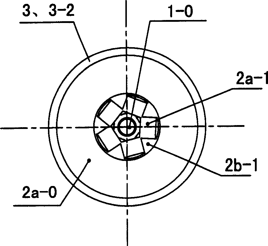
[0031] The internal main structure of the placement head frame is an upright multi-corrugated column or a cylinder wall 3, and the placement main shaft 1 is on the central axis of the inner cylinder 3 wall of the placement head; the drive motor The stators 2a-0 and 2b-0 of 2a and 2b are radially symmetrical and axially deeply fixed on the inner cylinder wall 3 of the placement head. Correspondingly, the movers of the drive motors 2a and 2b 2a-1, 2b-1 are radially symmetrical and fixedly installed...


PUM


Abstract

An integrated head of a plate overlayer includes a drive motor, a mainshaft and a suction mouth characterizing that the rotor of the motor is fixed on the mainshaft directly, the said stator of the motor is fixed on the frame of the head directly, the internal mainbody of the head frame is a vertical regular multiprism or cylinder tube wall, the said manshaft is placed at the axle wire of the internal tube wall of the head, the stator is fixedly mounted on the internal tube wall symmetric radially and longitudinal axially and the rotor is fixedly mounted on the surface of the mainshaft correspondingly.

Description

【Technical field】 [0001] The invention relates to the field of placement machines for electronic assembly, in particular to the technical field of a placement head assembly on a placement machine for electronic assembly. 【Background technique】 [0002] Printed circuit boards and integrated circuit chips are widely used spare parts in electronic information products, mechanical and electrical products, and household appliances. The electronic parts required for mounting and welding on printed circuit boards and integrated circuit chips Components, integrated circuits, logic circuits, etc., constitute functional electronic devices that can be used practically, and it is necessary to mount and weld the above-mentioned components with smaller and smaller sizes, various shapes and colors on printed circuit boards and integrated circuit chips. It is inseparable from the placement machine for electronic assembly that requires higher and higher precision and operational flexibility....

Claims


Application Information

Patent Timeline
Patent Type & Authority Applications(China)
IPC IPC(8): H05K3/30H05K13/04
Inventor 宋福民李萍陈真张小丽
Owner 广州市羊城科技实业有限公司
Learn More