Eureka AIR delivers breakthrough ideas for toughest innovation challenges, trusted by R&D personnel around the world.

Electrical control upright arrangement integrated pump / valve - pipe - nozzle spraying system

An in-line combination, injection system technology, applied in the charging system, electrical control, fuel injection control, etc., can solve the impossible control of fuel injection rate and fuel injection pressure, cannot directly change the fuel quantity and timing, and cannot achieve various Cylinder sub-cylinder control and other issues, to achieve the effect of being beneficial to system transplantation, simple structure, and simplified oil pump structure

Inactive Publication Date: 2005-01-26
TSINGHUA UNIV
View PDF1 Cites 8 Cited by
  • Summary
  • Abstract
  • Description
  • Claims
  • Application Information

AI Technical Summary

Problems solved by technology

This type of system has strong production inheritance and is easy to install. It can realize partial optimization of fuel quantity and timing. However, since the original fuel injection device and fuel injection characteristics have not changed, it is generally impossible to optimize the fuel injection rate and fuel injection. pressure regulation
In addition, because only position control can be performed, the oil volume and timing cannot be directly changed, there are many intermediate links, the control response is slow, and the cylinder-by-cylinder control of each cylinder cannot be achieved.

Method used


Image

  • Electrical control upright arrangement integrated pump / valve - pipe - nozzle spraying system

Examples


Embodiment Construction

[0011] The specific structure, working principle and preferred embodiments of the present invention will be described in detail below with reference to the accompanying drawings.

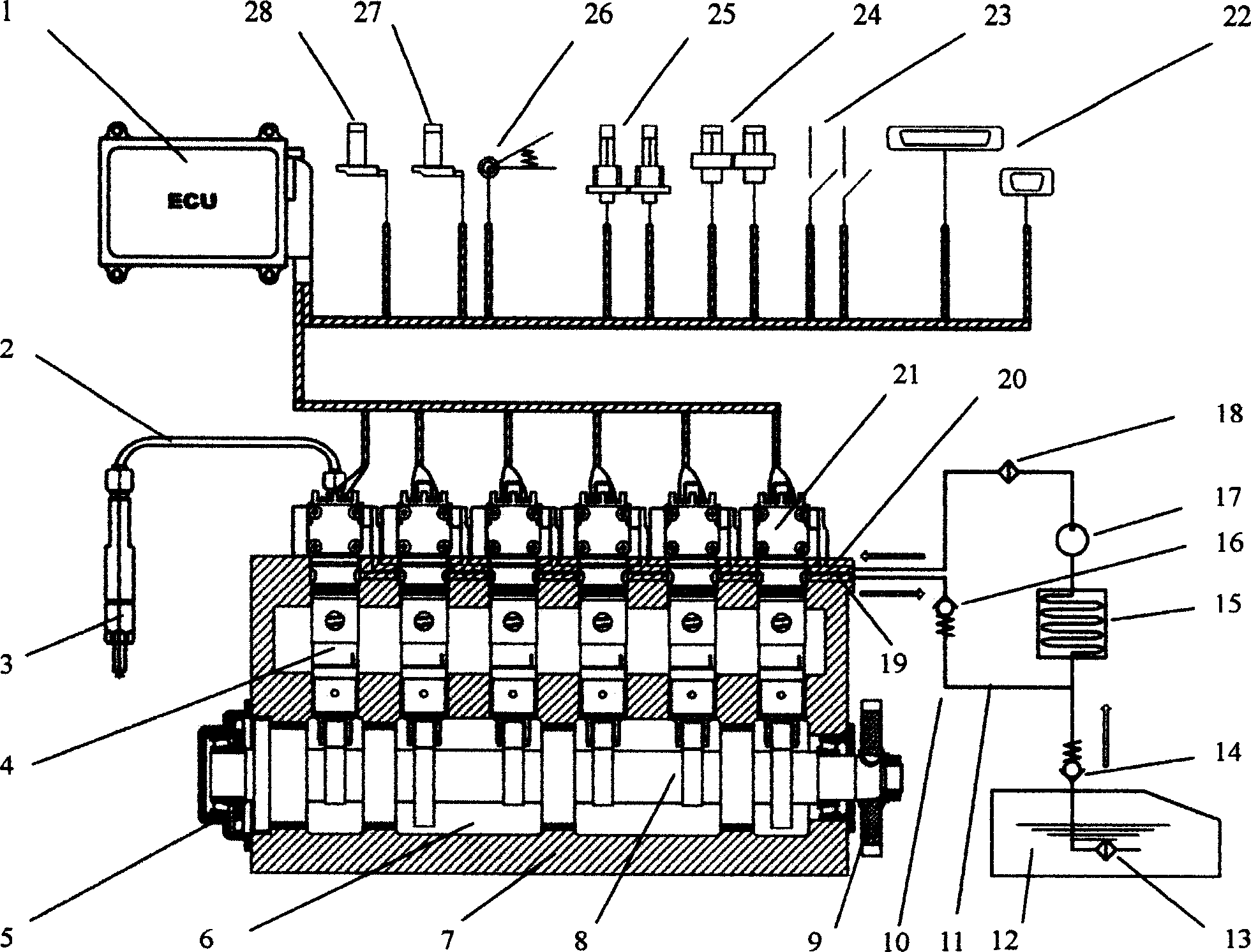
[0012] figure 1 Shown is the overall structure diagram of the electronically controlled inline combined pump / valve-pipe-nozzle diesel injection system. It mainly includes five functional modules: electronic control unit 1, in-line combined pump / valve device 6, high-pressure fuel pipe 2, fuel injector 3, and low-pressure fuel device 10:

[0013] The electronic control unit 1 consists of control system hardware based on a 32-bit single-chip microcomputer, engine management system software, a camshaft position sensor 28 installed on the pump body, a crankshaft position sensor 27 installed on the engine flywheel housing, and a crankshaft position sensor 27 installed on the accelerator pedal. The accelerator position sensor 26 is composed of various temperature sensors 25, pressure sensors 24, signal switch...


PUM


Abstract

This invention publicized belonged to the diesel engine fuel injection installment one kind of electric control in line combination to pump / the valve - tube - mouth to spray the diesel oil injection system. Should the injection system mainly include the electronic control unit, in line the combination pumps / the valve mechanism, the high-pressure oil pipe, the spray hole and the low pressure fuel oil system. The characteristic is in line the combination pumps / the valve mechanism plunger partner to use the direct jack-in type structure, in pump body in-line type arrangement; The plunger partner's plunger crown does not have the skewed slot, only undertakes for the oil and pressurizes the function; Integrates on in in the plunger partner plunger cavity high-pressured oil duct has the high speed solenoid valve module, solenoid valve coil and the electronic control unit is connected, by electronic control unit through solenoid valve direct control fuel injection process; This system not only causes the oil pump structure to simplify, the intensity increases, greatly enhanced has supplied the oil pressure, moreover caused for the oil process and the adjustment process decoupling, has realized through the high speed solenoid valve module to fuel injection the process direct digital control; The blow rule for a more ideal wedge, has the low initial blow rate, high host spraying rate, the fast high-pressured unloading and the remaining fluctuation of pressure are small and so on the merit: Also system layout simple, transforms few to the engine main body, the transplant is convenient.

Description

Technical field [0001] The invention relates to a diesel engine fuel injection device, in particular to an electronically controlled inline combined pump / valve-pipe-nozzle type diesel injection system. Background technique [0002] The traditional diesel pump-pipe-nozzle fuel injection system mainly includes three parts: in-line pump (or distribution pump), high-pressure fuel pipe and fuel injector. Typical systems include Bosch's P-type in-line pump system and VE-type distribution pump system. Take the P-type in-line pump as an example, the control of the oil volume is achieved through the governor pulling the rack to drive the plunger to rotate, thereby changing the relative position of the plunger spiral groove and the oil return hole; the control of the start of the fuel injection is through inertia The mechanism changes the relative positional relationship between the crankshaft of the diesel engine and the camshaft of the oil pump. The process of high pressure oil discharge...

Claims


Application Information

Patent Timeline
Patent Type & Authority Applications(China)
IPC IPC(8): F02D41/02F02D41/26F02D41/30F02M57/02
Inventor 欧阳明高李建秋杨福源李进安利强李希浩周明
Owner TSINGHUA UNIV
Why Eureka
Eureka Blog
Learn More