Multi-coil induction plasma torch for solid state power supply

A plasma and torch technology, applied in the direction of plasma, plasma welding equipment, electrical components, etc., can solve the problems of affecting the uniformity of the temperature field, reducing efficiency, and not being suitable for RF signals

Inactive Publication Date: 2005-01-26
泰克纳等子系统公司
View PDF0 Cites 12 Cited by
  • Summary
  • Abstract
  • Description
  • Claims
  • Application Information

AI Technical Summary

Problems solved by technology

[0013] However, solid state power supplies are now characterized by a low frequency operating range (typically between 300 and 400 Hz) and are therefore generally not suitable for the high frequency coil generation required for inductively igniting the plasma. RF signal
Moreover, applications for ignition and operation of plasma torches at atmospheric pressure or under low vacuum conditions have precluded the use of e

Method used


Image

  • Multi-coil induction plasma torch for solid state power supply
  • Multi-coil induction plasma torch for solid state power supply

Examples


Embodiment Construction

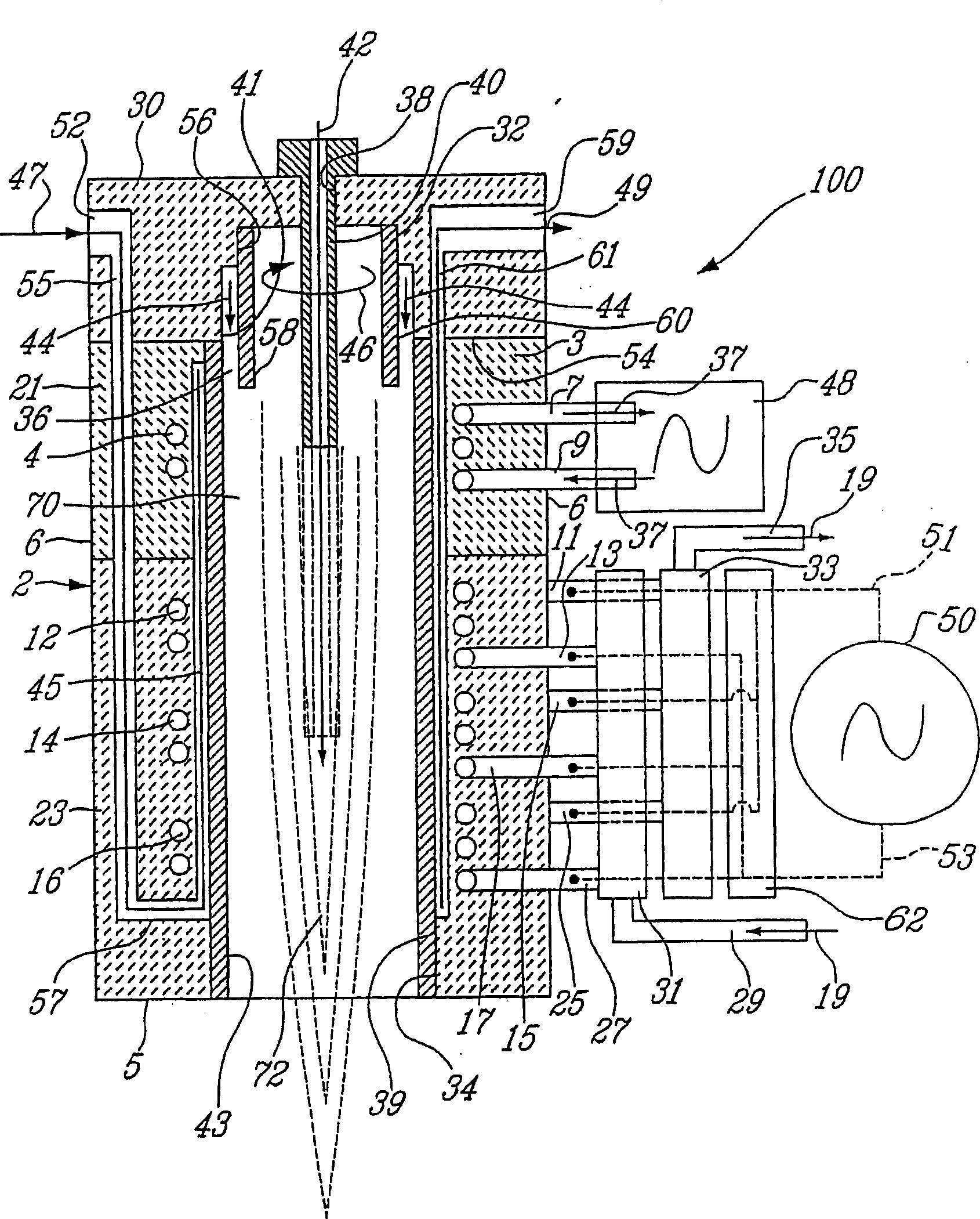
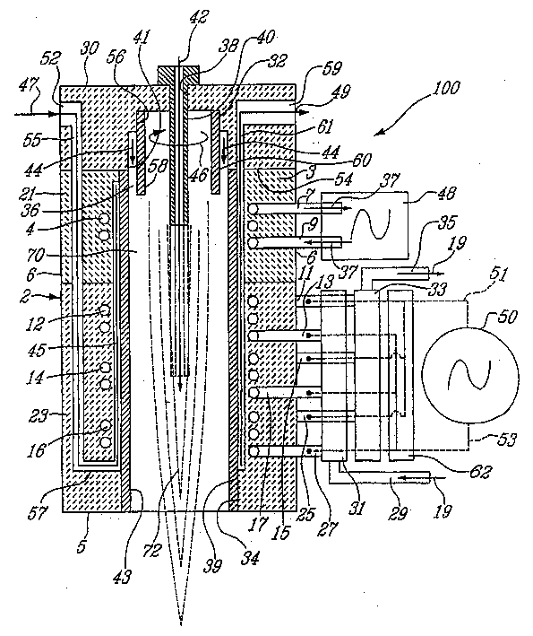
[0029] figure 1 is a multi-coil induction plasma torch generally indicated at 100 . Particularly figure 1 The illustrated exemplary embodiment forms a high impedance matched multi-coil induction plasma torch capable of generating an inductively coupled gas plasma.

[0030] figure 1 The multi-coil induction plasma torch 100 described in includes a tubular (eg cylindrical) torch body 2 consisting of proximal and distal tubular members 21 and 23 made of cast ceramic or composite polymer and Assembled end to end. Other suitable materials may also be used to manufacture the tubular members 21 and 23 of the flare body. The tubular flare body 2 has a proximal end 3 and a distal end 5 and defines an axial chamber 70 in which a plasma 72 is ignited and maintained.

[0031] still reference figure 1 In the exemplary embodiment shown, the tubular flare body 2 has an inner cylindrical surface lined with a relatively thin cylindrical plasma confinement tube 39 coaxial with the flare b...


PUM


Abstract

An induction plasma torch comprises a tubular torch body, a gas distributor head located at the proximal end of the torch body for supplying at least one gaseous substance into the chamber within the torch body, a higher frequency power supply connected to a first induction coil mounted coaxial to the tubular torch body, a lower frequency solid state power supply connected to a plurality of second induction coils mounted coaxial to the tubular torch body between the first induction coil and the distal end of this torch body. The first induction coil provides the inductive energy necessary to ignite the gaseous substance to form a plasma. The second induction coils provide the working energy necessary to operate the plasma torch. The second induction coils can be connected to the solid state power supply in series and/or in parallel to match the impedance of this solid state power supply.

Description

technical field [0001] The present invention relates to induction plasma torches, in particular but not limited to a multi-coil induction plasma torch. Background technique [0002] In an induction plasma torch, a strongly oscillating magnetic field is generated by an induction coil and applied to a gas passing through the coil to ionize the gas to create a plasma. Such plasma torches use the concept of inductive coupling consisting of inductively coupling a radio frequency (RF) field to the flowing gas. The inductive coupling heats the gas to high temperatures, typically 9000°C. At this temperature, the gas transforms into a plasma of positively charged ions and electrons. Plasma torches are generally used in spectral composition analysis, fine powder processing, material melting, chemical synthesis, waste decomposition and similar aspects. These high temperature applications are uniquely associated with plasmas. [0003] Early attempts to generate plasmas by induction ...

Claims


Application Information

Patent Timeline
IPC IPC(8): G01N21/73H05H1/00H05H1/30
CPCH05H1/30B23K10/00
Inventor 马厄·I·博洛斯杰齐·W·朱里威茨
Owner 泰克纳等子系统公司
Why Eureka
Try Eureka