Reciprocating-rotating power converting mechanism without crank, and its engine and compressor

A technology of rotating power and conversion mechanism, applied in the field of compressors and piston engines, can solve the problems of mechanical power conversion efficiency limitation, gear tooth impact, affecting service life, etc., to improve energy conversion efficiency, improve emission performance, piston structure, etc. simple effect

Inactive Publication Date: 2005-02-16
程远
View PDF0 Cites 7 Cited by
  • Summary
  • Abstract
  • Description
  • Claims
  • Application Information

AI Technical Summary

Problems solved by technology

[0003] The most widely used power conversion mechanism at present is the crankshaft-connecting rod mechanism. For example, since the piston engine was invented more than a hundred years ago, this traditional mechanism is still almost completely used; When the pressure is the highest, the rotational torque may be the smallest, but when the rotational torque gradually increases to the maximum, the working power has been attenuated by more than half; in addition, under the action of the constantly changing torque, the side pressure generated by the piston on the cylinder wall increases the resistance and intensifies the Wear between critical components
Its disadvantages are: because it adopts the design of "intermittent meshing between incomplete gear and rack", the teeth that mesh first will be subject to considerable impact, which will affect its service life; in addition, when the engine speed is in a large range When changing, the synchronous operation between the gear and the rack is not easy to control, and misalignment may occur, resulting in more serious consequences

Method used


Image

  • Reciprocating-rotating power converting mechanism without crank, and its engine and compressor
  • Reciprocating-rotating power converting mechanism without crank, and its engine and compressor
  • Reciprocating-rotating power converting mechanism without crank, and its engine and compressor

Examples


Embodiment 8

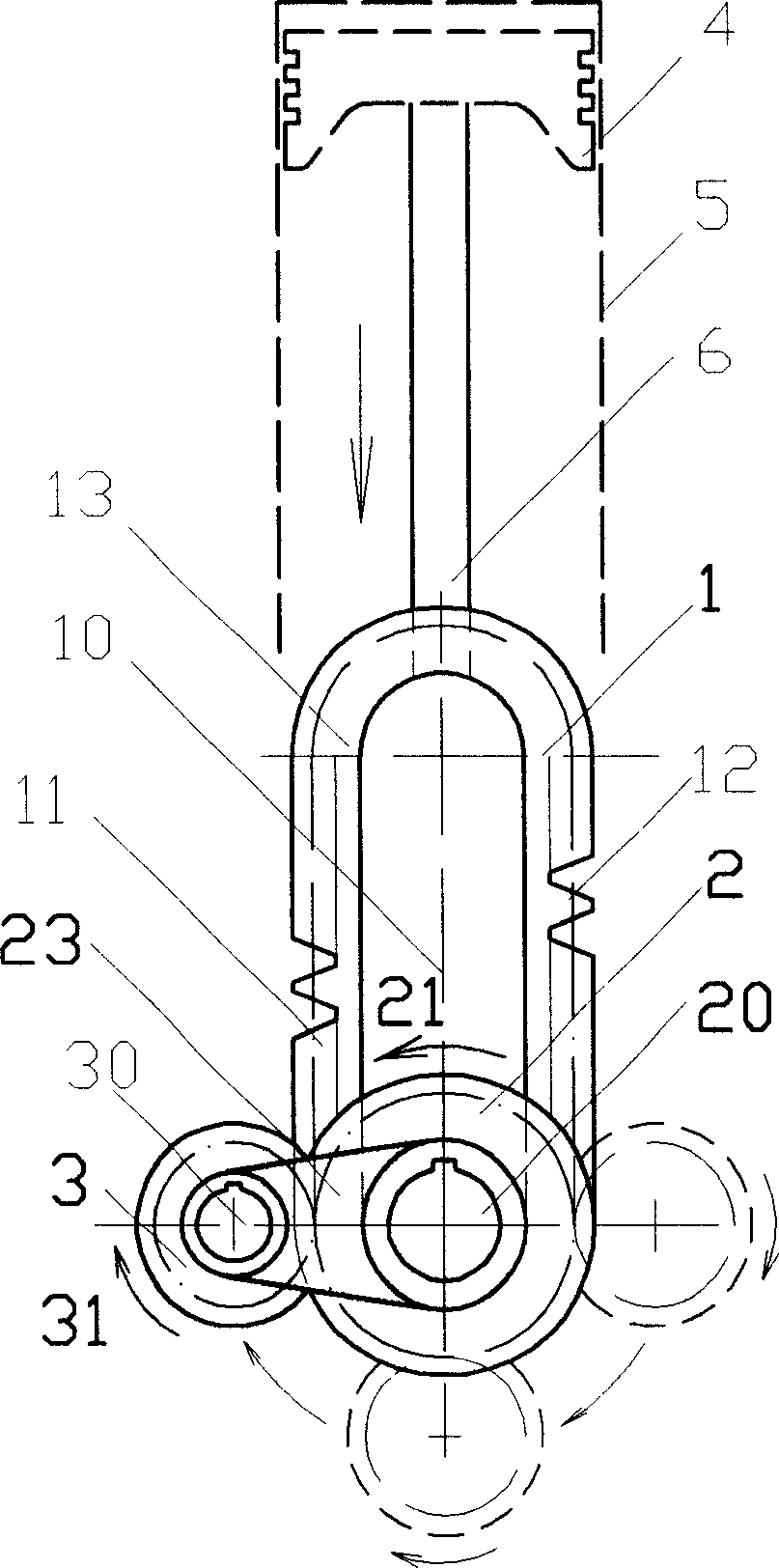
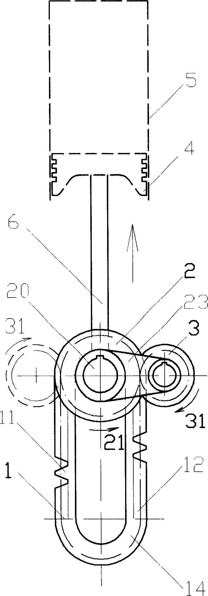
[0065] 2. In the above-mentioned embodiment, the planetary gear 3 can also be a gear train formed by coaxially connecting the front and rear gears 32, 33 (such as Figure 4 As shown), the front gear 32 is always directly meshed with the power gear 2, and the rear gear 33 is always directly meshed with the ring frame 1. The radii of the front and rear gears 32 and 33 can be the same or different: when the radii are the same, they can also be regarded as A long gear, similar to the previous example; when the radius is different, the radius of the power gear 2 and the radius of the semicircular gears 13, 14 at the two ends of the ring frame 1 can be different, so in the design, the relative size of their radii can be adjusted. Obtain different ratios of speed and torque output.

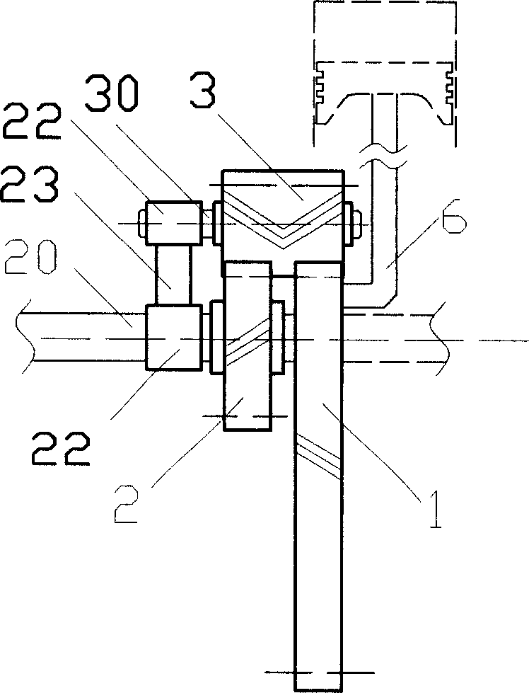
[0066] 3. In the above-mentioned embodiments, the power shaft 20 may not pass through the inside of the ring gear frame 1 (such as Figure 5 shown): At this time, the ring gear frame 1 can be a solid ri...


PUM


Abstract

The present invention discloses a reciprocating-rotating power converting mechanism without crankshaft, and its engine and compressor, wherein the power changeover mechanism consists of the alligatoring ring frame 1, the power wheel 2 and the planet wheel 3 connected with the reciprocating power unit replaces the conventional crankshaft connecting rod system; the planet wheel 3 adopting the power wheel 2 as a center wheel and adopting the pull rod 23 as a swiveling jib can revolute around the power shaft 20 and rotate, and is respectively in cross-over connection with the power wheel 2 and the alligatoring ring frame 1, though transmission parts such as wheel gears; the foreside and the rear are end respectively ganged with the power wheel 2 and the alligatoring ring frame 1; then the reciprocating movement of the alligatoring ring frame 1 can be transformed into the continuous rotating motion of the power wheel 2, and the continuous rotating motion of the power wheel 2 can alao be transformed into the periodic reciprocating movement of the alligatoring ring frame 1; said power changeover mechanism as well as engine and compressor etc. using the mechanism are characterized by simple structure, high transmission efficiency, high energy conversion efficiency, excellent discharging performances and the like.

Description

technical field [0001] The present invention relates to a power conversion mechanism for mutual conversion of reciprocating linear motion and rotary power; it also relates to a piston engine, a compressor, etc. using the power conversion mechanism. Background technique [0002] In the mechanical field, we often need to convert reciprocating motion and rotary power, especially piston engines (including gasoline, diesel, gas and other internal combustion engines, or steam engines, etc.), and piston air or refrigerant compressors, etc., their The main function needs to rely on this kind of power conversion mechanism to realize. [0003] The most widely used power conversion mechanism at present is the crankshaft-connecting rod mechanism. For example, since the piston engine was invented more than a hundred years ago, this traditional mechanism is still almost completely used; When the pressure is the highest, the rotational torque may be the small...

Claims


Application Information

Patent Timeline
Patent Type & Authority Applications(China)
IPC IPC(8): F01B9/04F02B75/32F04B27/10
Inventor 程远
Owner 程远
Why Eureka
Try Eureka