Vacuum smelting furnace

A vacuum melting furnace and melting chamber technology, applied in the direction of furnaces, crucible furnaces, furnace types, etc., can solve the problems of high energy consumption, complex structure, low extraction efficiency, etc., to improve production efficiency, prolong cleaning cycle, and improve production efficiency effect

Inactive Publication Date: 2005-03-16
SHENZHEN UNIV
View PDF2 Cites 10 Cited by
  • Summary
  • Abstract
  • Description
  • Claims
  • Application Information

AI Technical Summary

Problems solved by technology

[0003] In order to overcome the disadvantages of complex structure, low pumping efficiency and high energy consumption in existing vacuum melting

Method used


Image

  • Vacuum smelting furnace

Examples


Embodiment Construction

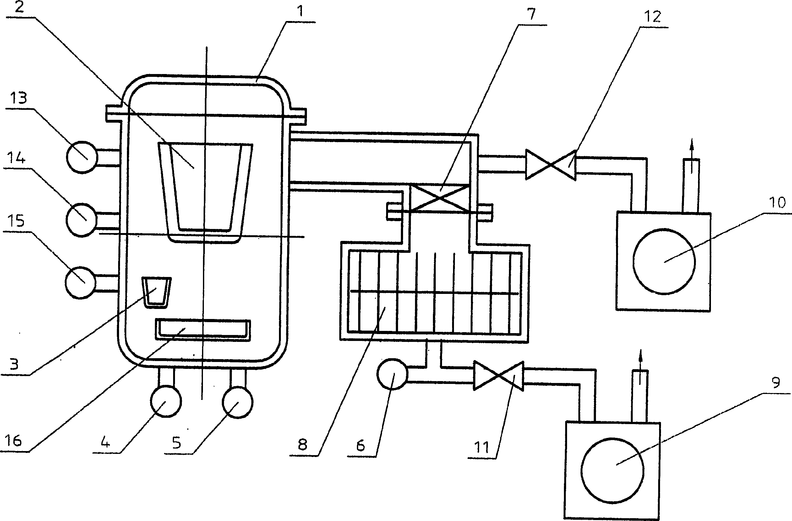
[0015] see figure 1 The vacuum melting furnace of the first embodiment of the present invention consists of a melting chamber 1, a crucible 2, an auxiliary evaporation source 3, a medium vacuum gauge 4, low vacuum gauges 5 and 6, a high vacuum valve 7, a traction molecular pump 8, and a backing vacuum pump 9 and 10, low vacuum valves 11 and 12, protective gas source 13, heating power supply 14, partial pressure monitor 15 and mold cavity 16.

[0016] Crucible 2, auxiliary evaporation source 3 and mold cavity 16 are located in melting chamber 1, medium vacuum gauge 4, low vacuum gauge 5, high vacuum valve 7, low vacuum valve 12, protective gas source 13, heating power supply 14 and partial pressure monitor 15 are respectively connected with the smelting chamber 1, the low vacuum valve 12 is also connected with the backing vacuum pump 10, the air inlet of the traction molecular pump 8 is connected with the high vacuum valve 7, the low vacuum gauge 6 and the low vacuum valve 11 a...


PUM


Abstract

Disclosed is a vacuum smelting furnace, comprising smelting chamber, bush, cavity, middle vacuum gauge, low vacuum gauge, high vacuum valve, vacuum pump, low vacuum valve, protective gas source and heat electric power source, and molecular drag pump whose are inlet is connected to the high vacuum valve, the low vacuum gauge and low vacuum valve are separately connected to air exhausting mouth of the molecular drag pump, besides, dust arrester, partial pressure monitoring meter and auxiliary evaporation source with active getter material are added between of the and air extracting channel. The vacuum smelting furnace is suitable for smelting of oxidable metal material and alloy, especially for permanent magnet alloy of rubidium-iron- boron. The invention has simple structure can reduce air extracting time and save energy, increase production efficiency and production quality.

Description

【Technical field】 [0001] The invention relates to a special metallurgy and material preparation, in particular to a vacuum melting furnace. 【Background technique】 [0002] Traditional vacuum melting furnace is composed of melting chamber, crucible, mold cavity, medium vacuum gauge, low vacuum gauge, high vacuum valve, Roots pump, oil diffusion pump, backing vacuum pump, low vacuum valve, protective gas source, heating power supply, etc. Among them, the Roots pump and the oil diffusion pump are the main suction pumps. This type of vacuum melting furnace has the disadvantages of complex structure, low pumping efficiency and high energy consumption. 【Content of invention】 [0003] In order to overcome the disadvantages of complex structure, low pumping efficiency and high energy consumption in existing vacuum melting furnaces, the present invention provides a vacuum melting furnace with simple structure, reduced pumping time and low pumping energy consumption. [0004] In o...

Claims


Application Information

Patent Timeline
IPC IPC(8): F27B14/04
Inventor 储继国范平龚建华
Owner SHENZHEN UNIV
Why Eureka
Try Eureka