Pre cooling type refrigeration method and pre cooling type treatment device for curing tumour

A technology of tumor treatment and refrigeration method, which is applied in the direction of cooling surgical instruments, etc., which can solve the problems of difficult air source, hindering the supply of nutrients to cells and the treatment of metabolites, and the great hidden dangers in the safety performance of cold knives, so as to achieve the reduction of air consumption Effect

Inactive Publication Date: 2005-06-15
北京库蓝医疗设备有限公司
View PDF0 Cites 11 Cited by
  • Summary
  • Abstract
  • Description
  • Claims
  • Application Information

AI Technical Summary

Problems solved by technology

[0006] 3. When metabolism continues, ice hinders the supply of cellular nutrients and the processing of metabolites, and cell death occurs
However, liquid nitrogen cryosurgical instruments are unsatisfactory in many respects
Evaporation of liquid nitrogen at the tip of the cryotip presents a serious problem: as it returns from the tip, the surrounding exhaust nitrogen heats part of the liquid nitrogen, which can evaporate the liquid nitrogen in the supply tube
However, the gas source pressure used by the argon-helium knife is very high, and the argon gas inlet pressure is higher than 210bar. It is specially prepared, and it is very difficult to obtain an air source, so the operation cost is also very high, and the cost of each operation exceeds 5,000 yuan
In addition, because the working pressure of argon gas is too high, that is, when the pressure drops to 210bar during use, it cannot be used, and a new argon gas bottle must be replaced in time, which results in the amount of gas available in a bottle It is very small, and one bottle of gas cannot even meet the needs of one operation, so the gas cylinder needs to be replaced during the operation, which causes great inconvenience to the operation and is likely to cause accidents

Method used


Image

  • Pre cooling type refrigeration method and pre cooling type treatment device for curing tumour
  • Pre cooling type refrigeration method and pre cooling type treatment device for curing tumour
  • Pre cooling type refrigeration method and pre cooling type treatment device for curing tumour

Examples


Embodiment 1

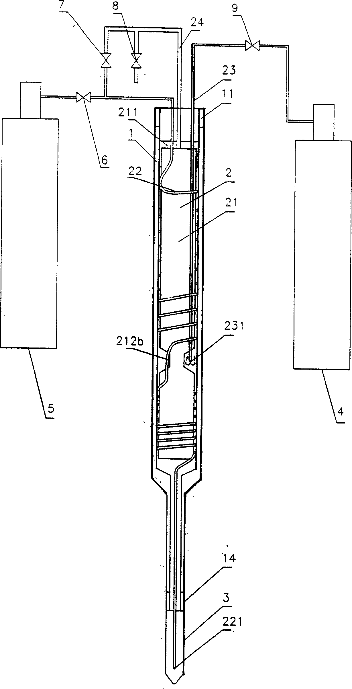
[0050] Such as figure 1 , when freezing, open the control valves 6, 8 and 9, and the high-pressure low-temperature working fluid flows from the gas cylinder 5 through the control valve 6 into the low-temperature working medium delivery pipe 22, and first passes through its front section, where it is combined with the high-temperature working medium from the middle of the connecting block. After heat exchange, it is pre-cooled to a certain temperature, enters the back section of the low-temperature working medium delivery pipe, and is further cooled by the low-temperature working medium that is throttled and returned, and throttles and reduces pressure at the throttle hole 221. Due to the J-T effect, it can Obtain the required low temperature; the high-temperature working medium enters the high-temperature working medium delivery pipe 23 through the control valve 9, and throttles and cools after passing through the orifice 231, and then from the upper inner wall of the outer wal...

Embodiment 2

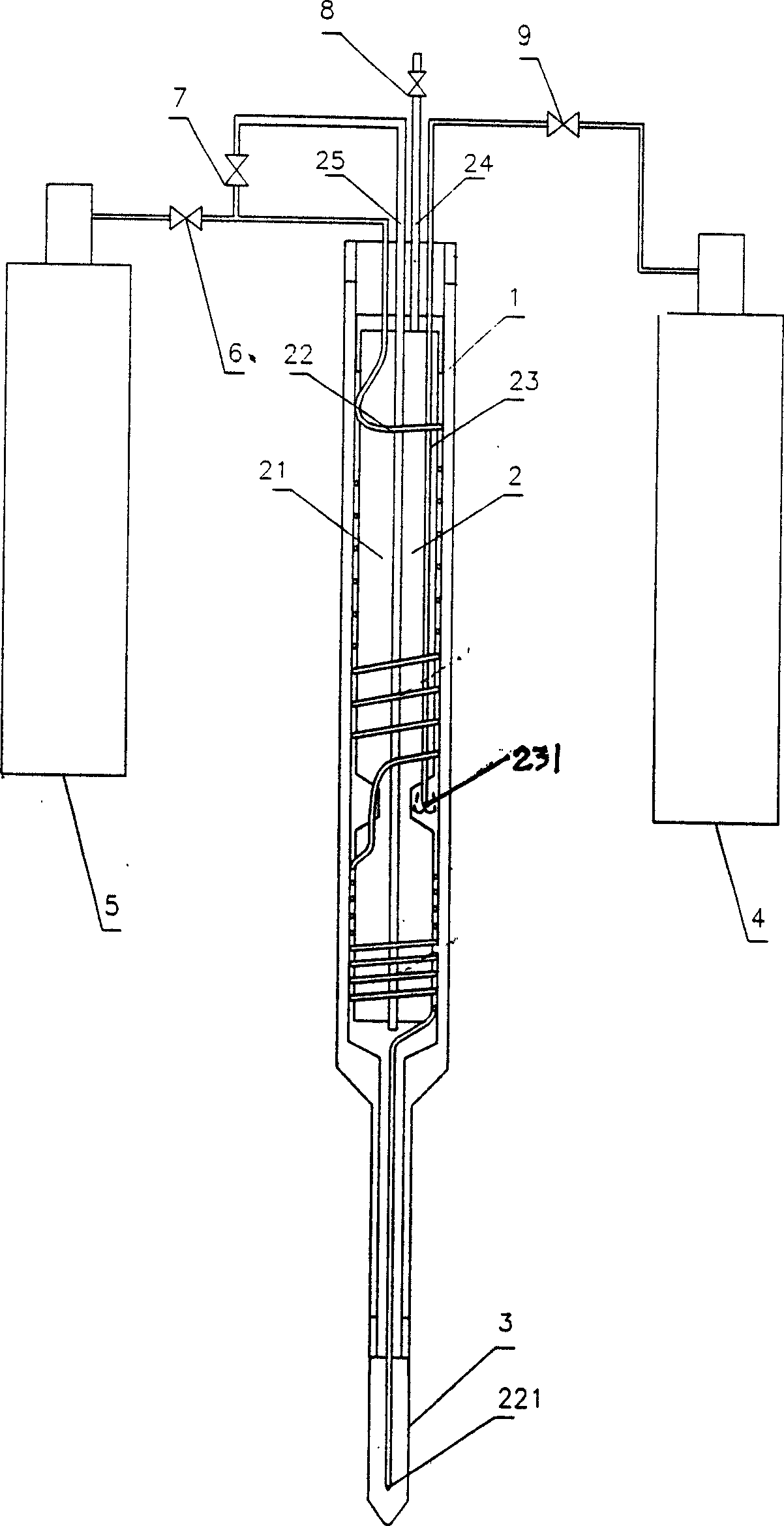
[0052] as attached figure 2 Shown, this is another embodiment of the present invention, this embodiment and the attached figure 1 The principles of the embodiments are basically the same, the low-temperature working medium is pre-cooled twice and reaches the lower part of the inner cavity of the probe head 3 through the delivery pipeline 22, where it is throttled and cooled to reach the required treatment temperature. The difference is that the air return pipe 24 is directly emptied after passing through the control valve 8 , and a return temperature pipe 25 is provided to extend to the lower end of the mandrel 21 . During the freezing process, the control valve 7 is closed, the control valves 6, 8 and the high-temperature working medium control valve 9 are opened, and the low-temperature working medium is sequentially throttled by the high-temperature working medium and returned from the probe head 3 when flowing through the delivery pipeline 22 The low-temperature working ...

Embodiment 4

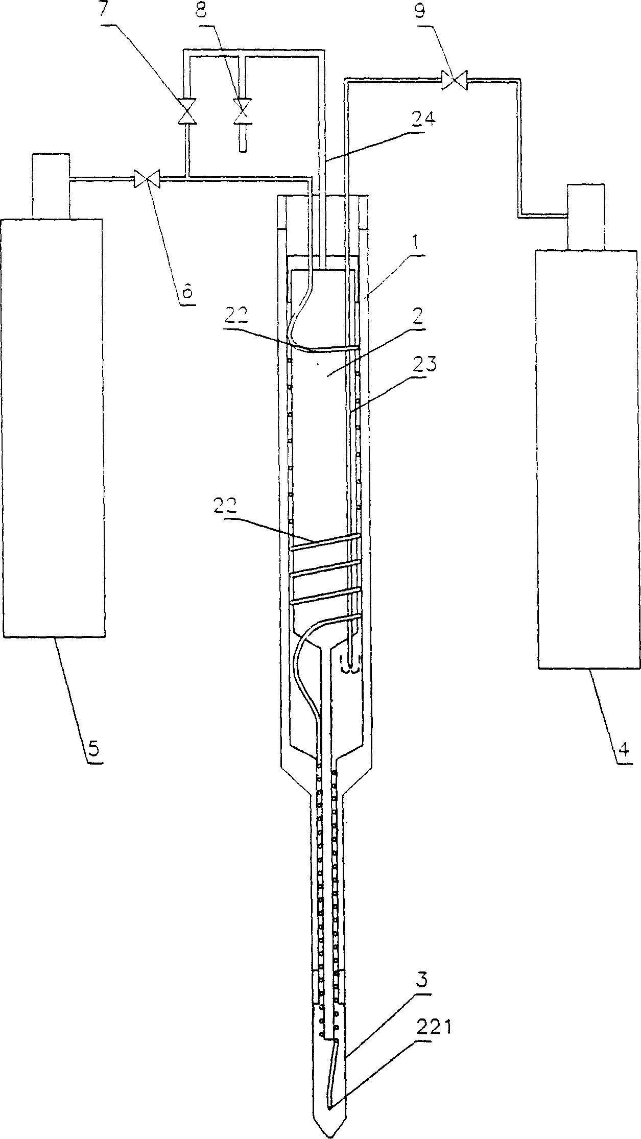
[0056] as attached Figure 4 As shown, this is the fourth embodiment of the present invention. In this embodiment, the mandrel 21 is a hollow cylinder. The air return pipe 24 is directly emptied after passing through the control valve 8, and the temperature return pipe 25 passes through the inner cavity of the mandrel and the outer tube and extends to the upper part of the inner cavity of the probe head 3. The front section of the low-temperature working fluid delivery pipeline is spirally wound on the outer wall of the mandrel 21 and is close to the inner wall of the outer tube to form a first-stage heat exchanger; The inner wall of the outer tube constitutes the second stage heat exchanger. The high-temperature working fluid delivery pipe 23 passes through the sealing plate 211 into the inner cavity of the mandrel 21 and passes through the end thereof. When returning to temperature like this, the high-pressure gas source directly passes through the temperature-returning pi...


PUM


Abstract

A pre-cooling refrigeration method and device for tumor treatment, comprising a vacuum jacket, a probe head, and a mandrel installed in the jacket, and a spirally arranged low-temperature working fluid connected to a low-temperature working gas source is wound on the peripheral wall of the mandrel. Quality delivery pipe, the front section constitutes the first-stage heat exchanger, the rear section constitutes the second-stage heat exchanger, and the lower end is provided with a small throttling hole and extends to the lower part of the probe head; There is a throttling hole at the end of the tube, and the high-temperature working fluid in it is throttled and refrigerated, and then the low-temperature working fluid in the low-temperature working medium delivery pipe is precooled, and the low-temperature working fluid passes through the throttling hole at the end of the delivery pipeline again. One-time throttling refrigeration, after reaching the predetermined temperature, it is delivered to the probe head for tumor treatment. The device has low working pressure, is easy to obtain, and has high safety, economy and stability.

Description

field of invention [0001] The invention belongs to the technical field of cryotherapy for surgery, and in particular relates to a precooling refrigeration method and a precooling treatment device for tumor treatment. technical background [0002] Surgery, the destruction of living tissue structures by freezing cells, is commonly used to destroy cancer cells or benign tumors. Compared with open surgery, cryogenic surgery has many advantages: it is quick, almost painless, does not require local anesthesia, has no risk of postoperative infection, and leaves almost no scars. [0003] Mechanisms of cell destruction by cryosurgery are: [0004] 1. If the tissue is cooled slowly, water leaves the cells, increasing the concentration of harmful electrolytes in the cells, resulting in tissue necrosis; [0005] 2. If the tissue is cooled rapidly, many and tiny ice crystals will be formed, making the ice crystals thinner, and the cells are not easily damaged at this time. But during ...

Claims


Application Information

Patent Timeline
Patent Type & Authority Applications(China)
IPC IPC(8): A61B18/02
Inventor 吴伟平赵行李浩明柯钢
Owner 北京库蓝医疗设备有限公司
Why Eureka
Try Eureka