Optical label switching structure supporting blocking mode and multiplexing control

A multiplexing and blocking mode technology, applied in the field of network structure, can solve the problem of unable to complete the packaging and unpacking of optical packets, adding optical marking heads, limiting the intelligence and flexibility of optical label switching, and distinguishing priority business classes by edge nodes, etc. problems, to achieve the effect of improving real-time characteristics and scalability characteristics, improving intelligence and flexibility, and improving bandwidth utilization

Inactive Publication Date: 2005-06-29
SHANGHAI JIAO TONG UNIV
View PDF0 Cites 10 Cited by
  • Summary
  • Abstract
  • Description
  • Claims
  • Application Information

AI Technical Summary

Problems solved by technology

The main defect of this switching method is that the wavelength routing channel must be established before data transmission, and the channel wavelength is always occupied and released until it is completed
[0003] Through literature retrieval to prior art, it is found that "Realization of Multi-wavelength Label" published by Shilin Xiao et al. in "IEEE Photonics Technology Letters" (Institute of Electrical and Electronics Engineers Photon Technology Letters) 2003, 15(4): 605-607 "Optical Packet Switching" (realization of multi-wavelength label optical packet switching), mentioned in this article is only the simplest optical label switching system, which cannot perform real-time terminal control on optical packets, cannot distinguish priority service classes at edge nodes, and cannot Completing the packaging and unpacking of optical packets and the addition of optical marking headers for arbitrary data streams, as well as complex functions such as programmable optical marking and optical packet time and optical packet interval delay, which severely limits the intelligence and flexibility of optical label switching, and even affects The real-time nature of the entire optical label switching system leads to the paralysis of the optical label switching network

Method used


Image

  • Optical label switching structure supporting blocking mode and multiplexing control
  • Optical label switching structure supporting blocking mode and multiplexing control
  • Optical label switching structure supporting blocking mode and multiplexing control

Examples


Embodiment Construction

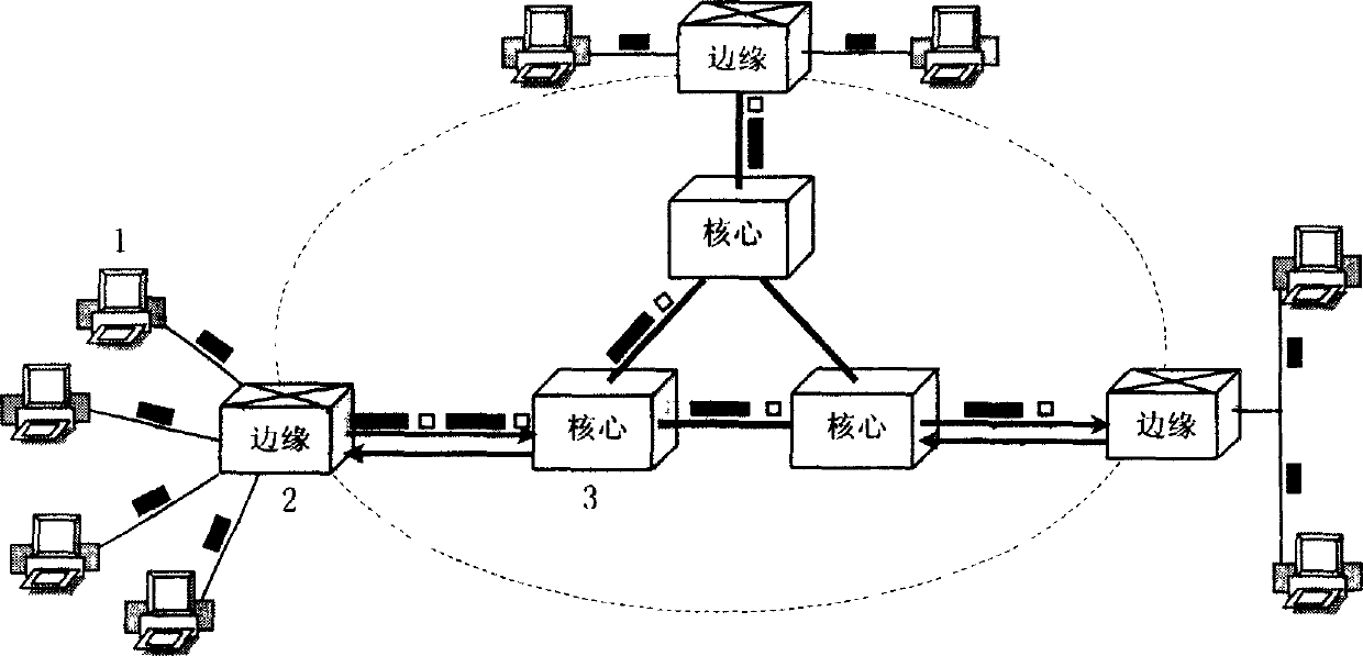
[0021]As shown in Figure 1, the OLS network structure of the present invention includes: a computer terminal 1, an OLS edge node 2, and an OLS core node 3, and the connection relationship is: four computer terminals 1 are connected to the OLS edge node 2 , three optical label switching core nodes 3 are interconnected, and are connected to three corresponding optical label switching edge nodes 2 at the same time, and the other two optical label switching edge nodes 2 are connected to two computer terminals 1 respectively. The low-speed camera capture signals or high-speed multimedia video streams generated by the four computer terminals 1 are aggregated in 10M / 100M electrical Ethernet packet format and connected to the optical label switching edge node 2, and the video signals of the computer terminals are aggregated at the optical label switching edge node 2. The priority of the service class and the destination address are classified and packaged into Gigabit optical Ethernet ...


PUM


Abstract

This invention relates to a mode of supporting block and an optical mark exchange structure controlled by multi-path multiplex. A computer end is connected with the exchange marginal nodes of optical mark, which are connected with the exchange core nodes, an electronic input / output wire card is connected into an optical packet bundle and de-packet processor, which is connected with light mark head generation module and a WDM device, in the core nodes, the input of WDM device connects the fibers arriving at the core nodes with the input of a light mark T-R processor and a light switch exchange matrix, the output of the processor and the matrix are connected with the output of the WDM device.

Description

technical field [0001] The invention relates to a network structure used in the technical field of optical communication, in particular to an optical label switching structure supporting blocking mode and multiplexing control. Background technique [0002] Optical switching can be divided into two modes: circuit switching and optical packet switching of wavelength routing. The optical switching mode of the former is circuit switching, the basic switching unit is a call, and the bandwidth of the entire call is reserved in both directions. The main defect of this switching method is that the wavelength routing channel must be established before data transmission, and the channel wavelength is always occupied and released until it is completed. A more ideal optical switching method is of course optical packet switching. It divides the optical information into optical load groups with a fixed length, and then adds optical headers carrying routing information to form optical in...

Claims


Application Information

Patent Timeline
Patent Type & Authority Applications(China)
IPC IPC(8): H04J14/02H04L12/701H04L12/801
Inventor 隋志成曾庆济肖石林
Owner SHANGHAI JIAO TONG UNIV
Why Eureka
Try Eureka