An impedance imaging method and apparatus

An impedance imaging and imaging technology, applied in the field of medical imaging, can solve the problems of difficulty in measuring the disturbance field, electrodes affecting the impedance distribution image, and difficulty in passing the injected current.

Inactive Publication Date: 2005-07-06
INST OF ELECTRICAL ENG CHINESE ACAD OF SCI
View PDF1 Cites 12 Cited by
  • Summary
  • Abstract
  • Description
  • Claims
  • Application Information

AI Technical Summary

Problems solved by technology

The problems with this imaging method are: (1) It is very difficult to measure the disturbance field generated by the induced current inside the imaging target
There are some problems in this method of injecting current, mainly: (1) the electrodes placed on the surface of the imaging target have contact impedance, so the placement of the electrodes affects the impedance distribution image to a large extent; (2) if If there is a current shield in the imaging target, such as the skull in the human brain, it is difficult for the injected current to pass through, thus affecting the imaging effect

Method used


Image

  • An impedance imaging method and apparatus
  • An impedance imaging method and apparatus
  • An impedance imaging method and apparatus

Examples


Embodiment Construction

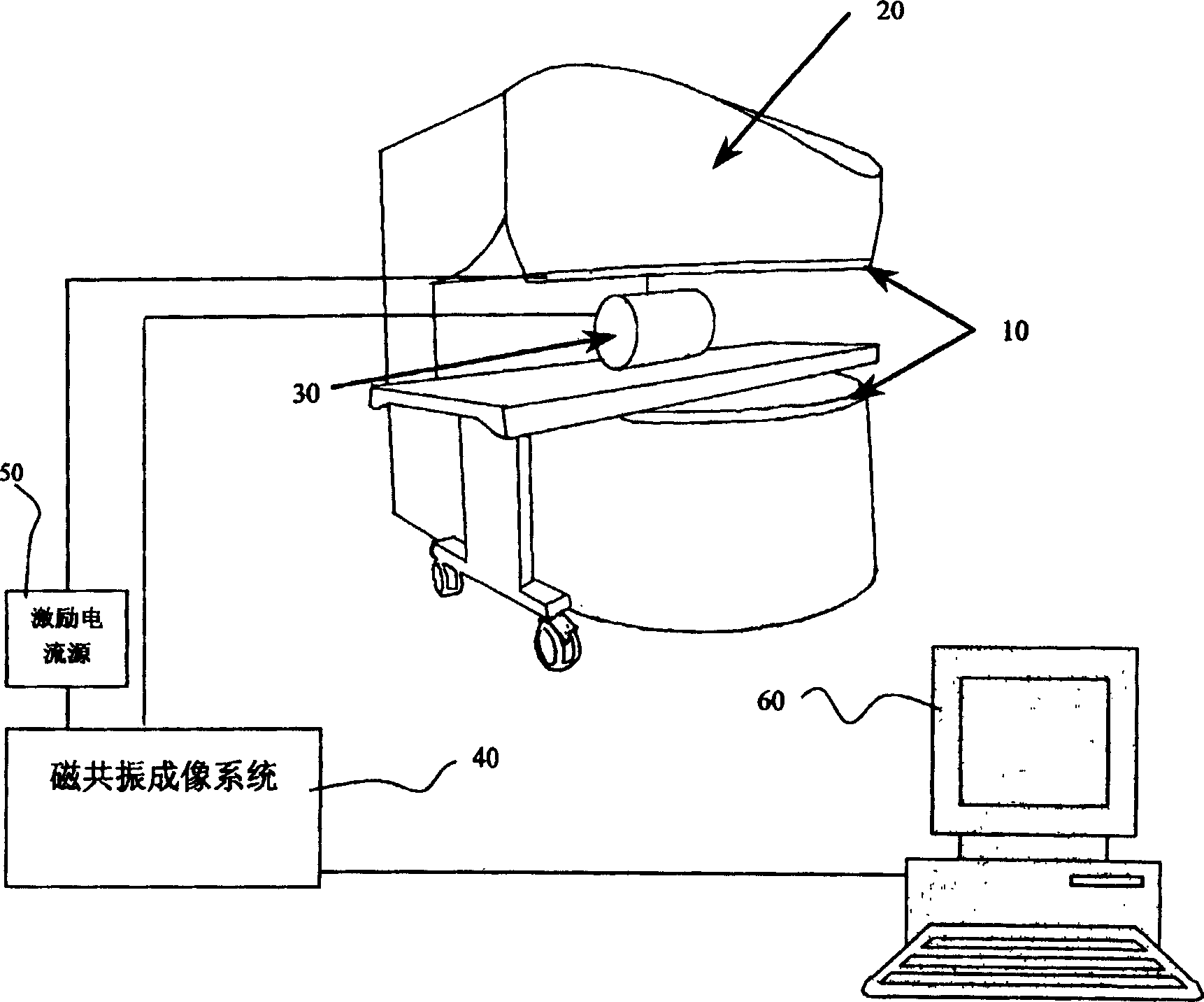
[0059] figure 2 It is a specific embodiment of the magnetic resonance magnetic induction imaging device applying the method of the present invention. Such as figure 2 Shown:

[0060] A pair of Helmholtz-type inductive excitation coils 10 are installed above the radio frequency coils on the upper and lower pole plates of the magnetic resonance imaging magnet, and the spacing between the two coils equals the radius of the coils. In this embodiment, radius=spacing=400mm, by Φ5mm Winding thick copper wire, the number of turns is 10 turns, and the excitation current is 80 amperes, then a magnetic field of about 20Gs with a uniformity of 0.3% can be generated in the imaging area of ​​a 20cm sphere. The power amplification of one control signal of the magnetic resonance spectrometer is used as the current source 50 for exciting the coil, the terminal voltage of the current source is 120V, and the maximum output current is 80A. The magnetic resonance imaging system 40 includes an...


PUM


Abstract

This invention relates to an impedance image forming method, which uses exciting coil to generate alternating field and generate inductance current in the target according to the magnetoelectric induction principles and influence the exciting alternating field distribution and adopts the magnetic resonance image forming technique to measure the field distribution in target. The image forming device comprises the exciting coil, magnetic resonance magnetism, radio frequency coil and step coil, magnetic resonance signal receiving coil, magnetic resonance image forming system and exciting current power and computer, wherein the exciting coil is a pair of Helmholtz coil fixed on the upper and down electrode plates of the open magnetic resonance image forming system radio frequency coil.

Description

technical field [0001] The invention relates to a medical imaging method, in particular to an impedance imaging method and device using magnetic resonance imaging technology and magnetic induction principle. Background technique [0002] Magnetic induction tomography (MIT for short) is an imaging method based on the basic principle that different biological tissues have different electromagnetic properties such as electrical conductivity and dielectric constant. Such as figure 1 As shown, when the biological tissue is placed in the exciting magnetic field B generated by the exciting coil 1, different eddy currents are induced in it, and the magnetic field B when there is biological tissue induced by the receiving coil 2 R And the relationship between the magnetic field B when there is no biological tissue and the conductivity and permittivity of the tissue is: [0003] B R - B ...

Claims


Application Information

Patent Timeline
Patent Type & Authority Applications(China)
IPC IPC(8): A61B5/055G01R33/20
Inventor 王慧贤刘国强杨文晖
Owner INST OF ELECTRICAL ENG CHINESE ACAD OF SCI
Why Eureka
Try Eureka