Method and apparatus for gas treatment using non-equilibrium plasma

A gas treatment and plasma technology, applied in the direction of plasma, gas treatment, separation methods, etc., can solve the problems of high cost, low energy efficiency, low efficiency of intermediate products and decomposition treatment, etc., and achieve the effect of reducing cost

Inactive Publication Date: 2005-08-17
YAMAHA CORP +1
View PDF3 Cites 16 Cited by
  • Summary
  • Abstract
  • Description
  • Claims
  • Application Information

AI Technical Summary

Problems solved by technology

[0012] Conventional gas treatment methods suffer from various problems due to energy inefficiency, generation of undesired intermediate products, and inefficient decomposition processes
[0013] In particular, pulsed streamer discharges are relatively costly and impractical due to the need for a high-voltage pulse generator to generate pulses with surge
[0014] In order to improve the efficiency of decomposition treatment, various methods using a photocatalyst such as titanium dioxide and using an adsorbent such as aluminum are available; however, a substance having high efficiency as both a catalyst and an adsorbent cannot be provided in general
Due to the inability to suppress nitrogen oxides (NO X ), so spot discharges (or packed bed discharges) using photocatalysts such as titania have many problems
Therefore, the aforementioned problems have not been resolved

Method used


Image

  • Method and apparatus for gas treatment using non-equilibrium plasma
  • Method and apparatus for gas treatment using non-equilibrium plasma
  • Method and apparatus for gas treatment using non-equilibrium plasma

Examples


no. 1 approach

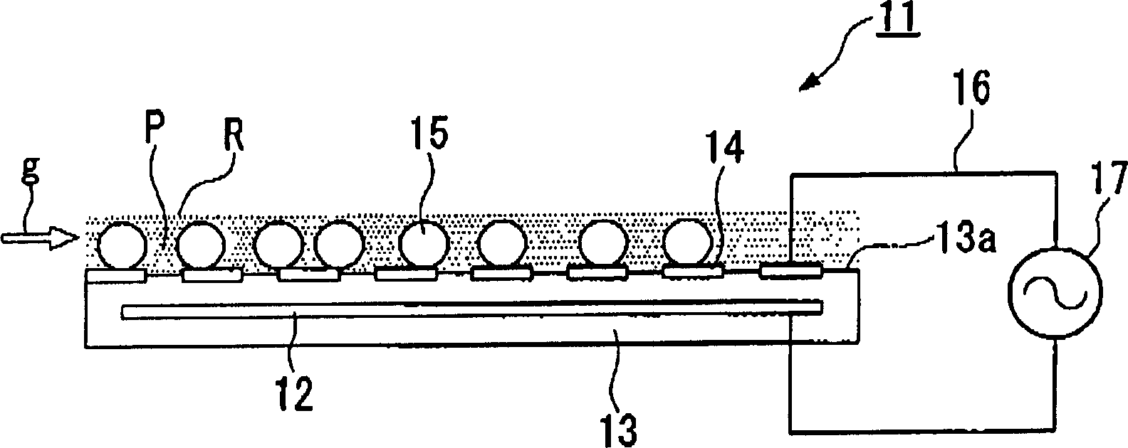
[0043] figure 1 The structure of the surface discharge electrode used in the gas treatment device according to the first embodiment of the present invention is schematically shown.

[0044] Such as figure 1 As shown, the surface discharge electrode 11 is generally formed as a disk-shaped plate electrode, wherein it includes a thin disk-shaped ground electrode 12, a thick disk-shaped insulator 13 containing the ground electrode 12, and an upper surface (or main surface) 13a of the insulator 13. A plurality of spiral surface electrodes 14 and a plurality of photocatalyst members 15 formed on the surface, each photocatalyst member containing photocatalyst and solid matter (not containing photocatalyst), and these photocatalyst members are arranged in the non-equilibrium plasma region R, Wherein the ground electrode 12 and the surface electrode 14 are connected to a power source 17 through a wire 16 .

[0045] The shape and size of the above-mentioned surface electrodes 11 are...

no. 2 approach

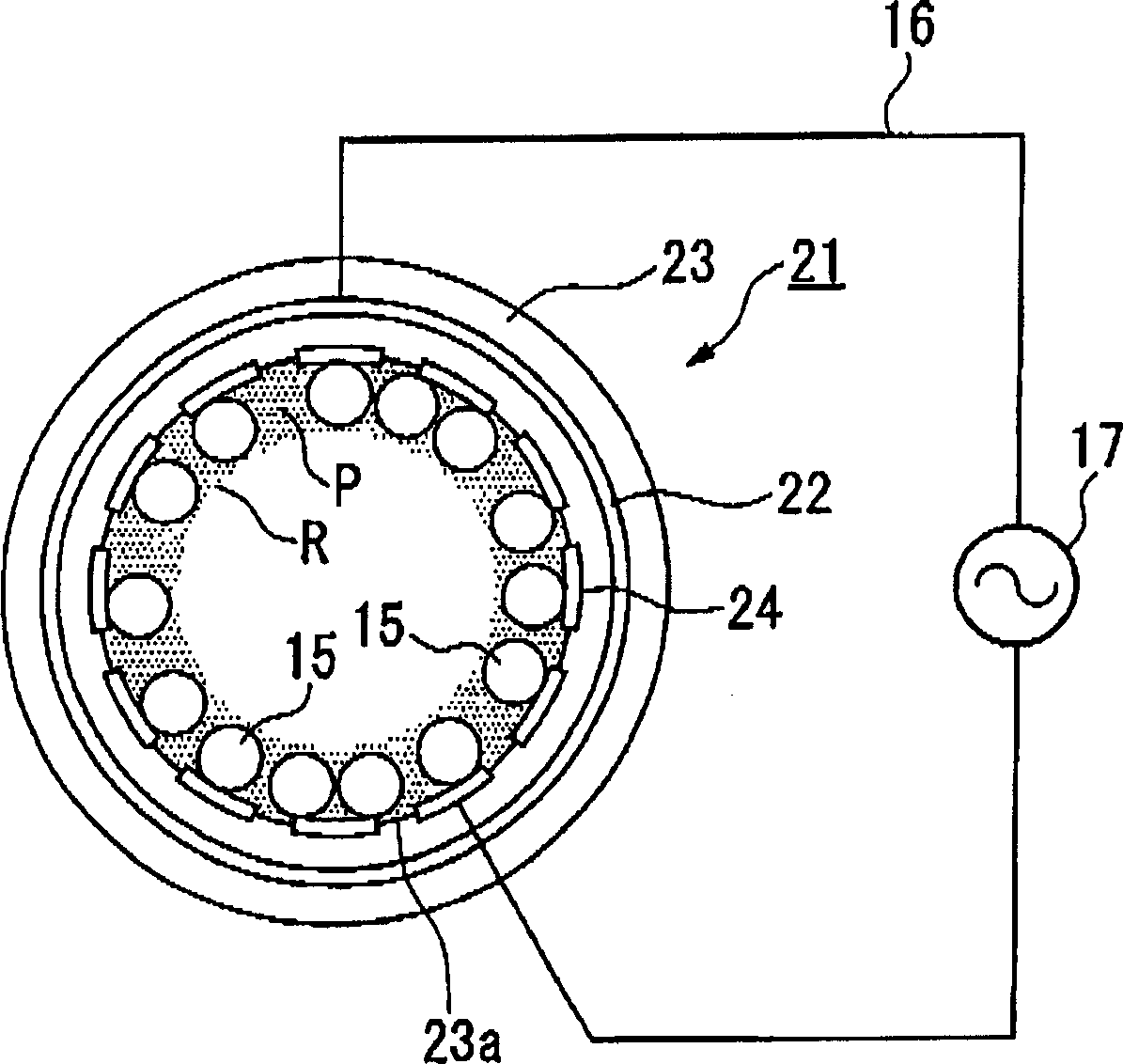
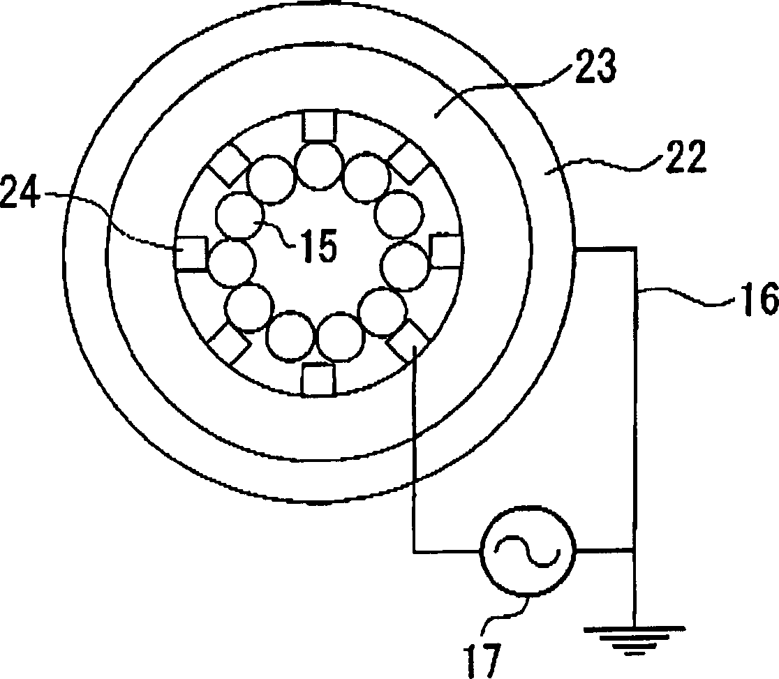
[0081] figure 2 The structure of a surface discharge electrode used in a gas treatment device according to a second embodiment of the present invention is schematically given, wherein the same reference numerals are used to designate the same as in figure 1 shown in the first

[0082] Implementation of the same components.

[0083] The surface discharge electrode 21 includes a tubular (or cylindrical) ground electrode 22 made of a conductive material; a tubular (or cylindrical) insulator 23 made of an insulating material; the insulator surrounds the ground electrode 22 in a closed state; and each A plurality of surface electrodes 24, which are all strip-shaped, are arranged on the inner peripheral wall 23a of the insulator 23 in a coaxial manner with the ground electrode 22; and photocatalysts arranged in the non-equilibrium plasma region R on the surface electrodes 24 Component 15 (including photocatalyst and solid matter). All surface electrodes 24 are connected to a po...

no. 3 approach

[0088] Figure 4 is a sectional view showing main parts of a gas treatment apparatus according to a third embodiment of the present invention, in which the same reference numerals as in figure 1 The same components as shown in the first embodiment.

[0089] The gas treatment device 31 is installed in an exhaust pipe arranged in an incinerator for processing general waste and industrial waste in which a plurality of surface discharge electrodes 34 block the exhaust gas from flowing through the exhaust pipe 35 These surface discharge electrodes 34 ( Figure 4 Three groups of surface discharge electrodes 34 arranged in parallel with a specified electrode spacing are shown). The space between adjacently arranged surface discharge electrodes 34 is filled with a plurality of photocatalyst members 15 each including a photocatalyst and a solid substance. The surface discharge electrode 34 includes the ground electrode 12 serving as a rectangular thin plate electrode, the insulator...


PUM

PropertyMeasurementUnit
specific surface areaaaaaaaaaaa

Abstract

A gas treatment method is actualized by arranging a plurality of photocatalyst members each including photocatalyst, solid substance, and catalyst in a region of non-equilibrium plasma, which is produced using a surface discharge electrode and into which a treated gas such as an exhaust gas and a harmful gas including harmful chemical substances is introduced and is then subjected to decomposition. The surface discharge electrode comprises a ground electrode, an insulator encompassing the ground electrode, and a plurality of surface electrodes that are arranged relative to the ground electrode via the insulator, by which the non-equilibrium plasma is produced upon electrification. A gas treatment apparatus is constituted by arranging a plurality of surface discharge electrodes, each having a plurality of through holes penetrating in a thickness direction, between which a plurality of photocatalyst members are arranged.

Description

technical field [0001] The present invention relates to a gas treatment method and apparatus using non-equilibrium plasma generated by surface discharge electrodes. [0002] This application claims priority from Japanese Patent Application No. 2003-364898, the contents of which are hereby incorporated by reference. Background technique [0003] Exhaust gases from general waste and industrial waste incinerators include, for example, NO X , SO X and dioxin harmful chemicals. In order to avoid environmental pollution and undesired effects on the human body, it is required to decompose the harmful gas containing harmful chemical substances into a harmless gas before being discharged into the atmosphere. [0004] Generally, various gas treatment methods have been developed as a method for decomposing and treating harmful gases, and among them, a specific gas treatment method using electric discharge has been developed and put into practical use. The advantage of this gas trea...

Claims


Application Information

Patent Timeline
Patent Type & Authority Applications(China)
IPC IPC(8): B01D53/32B01D53/74B01D53/86B01J19/08B01J23/00F01N3/08F01N3/20H05H1/24
CPCF01N3/2086F01N3/0892B01D53/32B01D2255/802Y02T10/26B01D2259/818H05H1/24Y02T10/12H05H1/2425H05H1/2437H05H1/2443H05H1/2418H05H2245/15H05H1/2439
Inventor 室井国昌尾形敦
Owner YAMAHA CORP
Why Eureka
Try Eureka