

Small displacement high lift reciprocating submersible electric pump
A submersible electric pump, high-lift technology, applied in the direction of pumps, liquid variable capacity machinery, pumps with flexible working elements, etc., can solve the problems of high maintenance cost, high investment cost and narrow application range.
- Summary
- Abstract
- Description
- Claims
- Application Information
AI Technical Summary
Problems solved by technology
Method used
Image

Examples
specific Embodiment approach 1
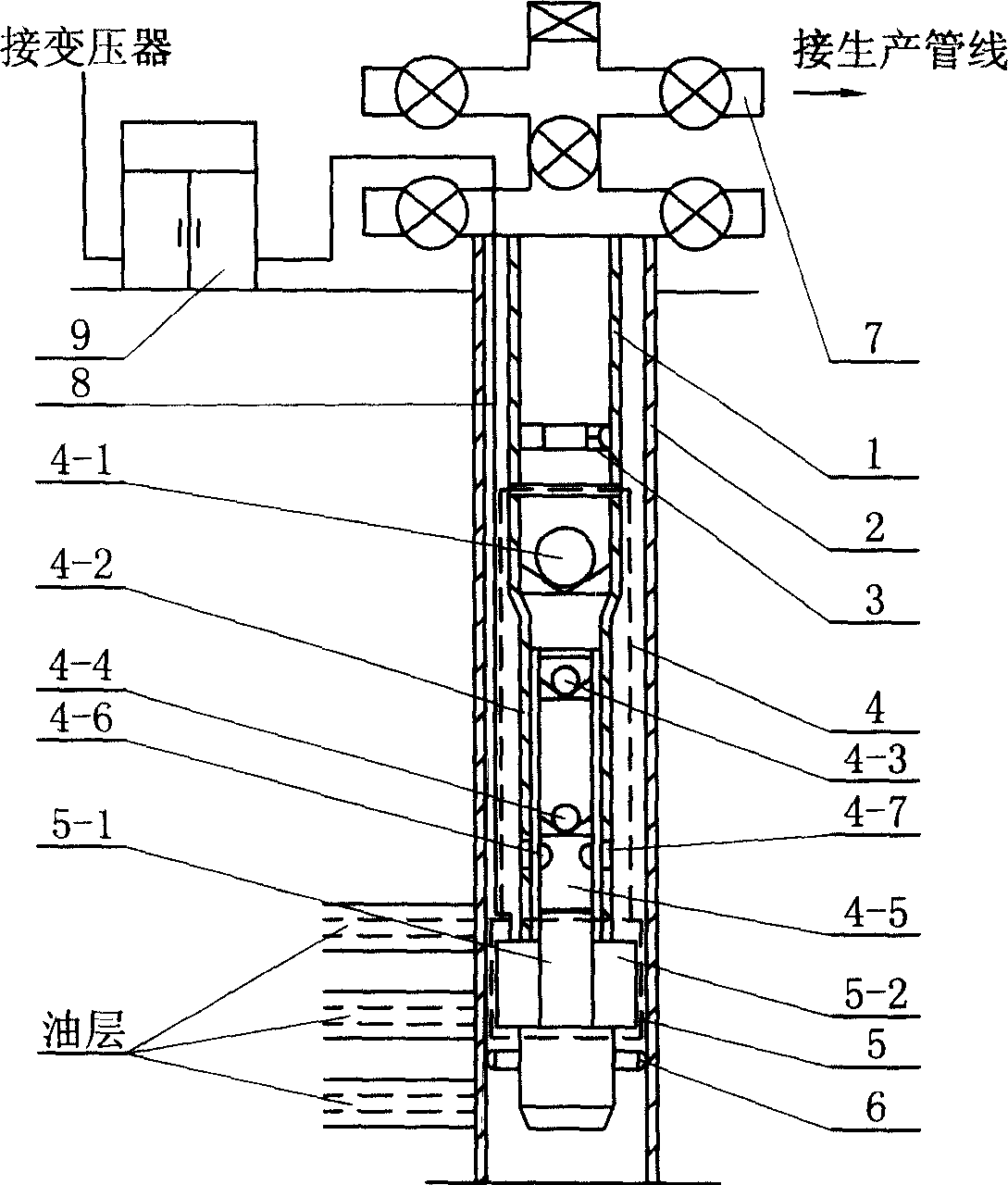
[0005] Specific implementation mode one: (see figure 1 ) This embodiment consists of tubing 1, casing 2, plunger pump 4, motor 5, centralizer or tubing anchor 6, wellhead 7, cable 8, frequency conversion speed control device 9; wellhead 7 is fixed on casing 2 The upper end of the oil pipe 1 is set in the casing 2, the upper end of the oil pipe 1 is fixedly connected with the lower end of the wellhead 7, the outlet end of the plunger type oil well pump 4 is fixedly connected with the lower end of the oil pipe 1, and the lower end of the plunger type oil well pump 4 is connected with the lower end of the wellhead 7. The upper end of the motor 5 is fixedly connected, the lower end of the stator 5-2 of the motor 5 is fixedly connected with the upper end of the centralizer or the oil pipe anchor 6 fixed in the casing 2, one end of the cable 8 is connected with the terminal of the motor 5, and the cable 8 The other end is connected with the frequency conversion speed regulation cont...
specific Embodiment approach 2
[0006] Specific implementation mode two: (see figure 1 ) The difference between this embodiment and the first embodiment is that an oil drainer 3 is fixed inside the oil pipe 1 . Other compositions and connections are the same as in the first embodiment. The function of the drainer 3 is to put in tools to open the channel of the drainer during the secondary construction operation, so that the annular space between the oil pipe and the casing is connected, and the oil pipe is replaced with clean water or replacement fluid to make the oil in the oil pipe It enters the annular space of the oil pipe and the casing during operation, so that the oil pollution is not brought to the ground, and the construction is safe and environmentally friendly.
specific Embodiment approach 3
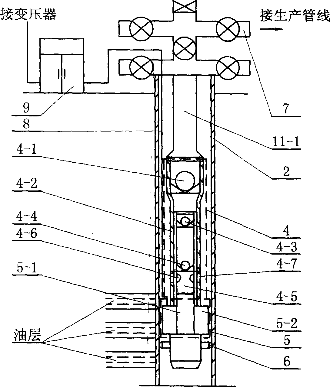
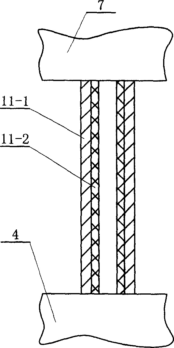
[0007] Specific implementation mode three: (see figure 2 , image 3 ) The difference between this embodiment and the first embodiment is that the oil pipe 1 is replaced by a flexible rope 11-1 and a small-diameter pipe 11-2. The small-diameter pipe 11-2 is arranged in the flexible rope 11-1, and the upper end of the flexible rope 11-1 and the small-diameter pipe 11-2 is fixedly connected with the lower end of the wellhead 7, and the flexible rope 11-1 and the small-diameter pipe 11-2 The lower end is fixedly connected with the upper end of the plunger type oil well pump 4 . The flexible rope 11-1 is a steel wire rope or a chain rope. The inner diameter of the small-diameter tube 11-2 is 20-50 mm. The small diameter pipe 11-2 is made of steel, iron, aluminum alloy or plastic. Other compositions and connections are the same as in the first embodiment.
PUM
| Property | Measurement | Unit |
|---|---|---|
| Tube inner diameter | aaaaa | aaaaa |
Abstract
Description
Claims
Application Information