Module type tubular solid oxide fuel cell power generating system

A solid oxide, fuel cell technology, used in solid electrolyte fuel cells, fuel cells, electrochemical generators, etc., can solve the problem of reducing the heating efficiency of the combustion chamber to the battery body and fuel gas, affecting fuel transmission and reaction, and affecting power generation. System performance and other issues, to solve the high temperature oxidation problem, the reformation effect is good, and the battery performance is improved.

Inactive Publication Date: 2005-09-28
JILIN UNIV
View PDF0 Cites 8 Cited by
  • Summary
  • Abstract
  • Description
  • Claims
  • Application Information

AI Technical Summary

Problems solved by technology

[0003] The existing technology has a compact structure between single cells and a high degree of development, but there are also many shortcomings: First, the battery body and the combustion chamber are independent, thereby increasing the sealing link, increasing the height of the overall system, and reducing the combustion chamber. Heating efficiency of battery body and fuel gas (hydrogen)
Second, the electrode connection is through the convex groove of the cathode and the groove of the anode. It is required that the electrolyte tube cannot be bent or deformed a little bit. Damage; In addition, the connection of the electrode lead is prone to oxidation in the high temperature range of 800-1000 °C
Third, pure hydrogen is expensive as a fuel, and there are safety issues in transportation and storage, which limits the civilian market; if natural gas or city gas is used, external reforming equipment for fuel is required, and direct internal reforming without additional equipment will be expensive. Cause excessive carbon deposition on the surface of the anode, block the electrode channel, affect the transmission and reaction of fuel on the anode surface, reduce the surface activity of the electrode, and thus affect the performance of the power generation system

Method used


Image

  • Module type tubular solid oxide fuel cell power generating system
  • Module type tubular solid oxide fuel cell power generating system
  • Module type tubular solid oxide fuel cell power generating system

Examples


Embodiment 1

[0023] Embodiment 1 Modular cell structure of the present invention

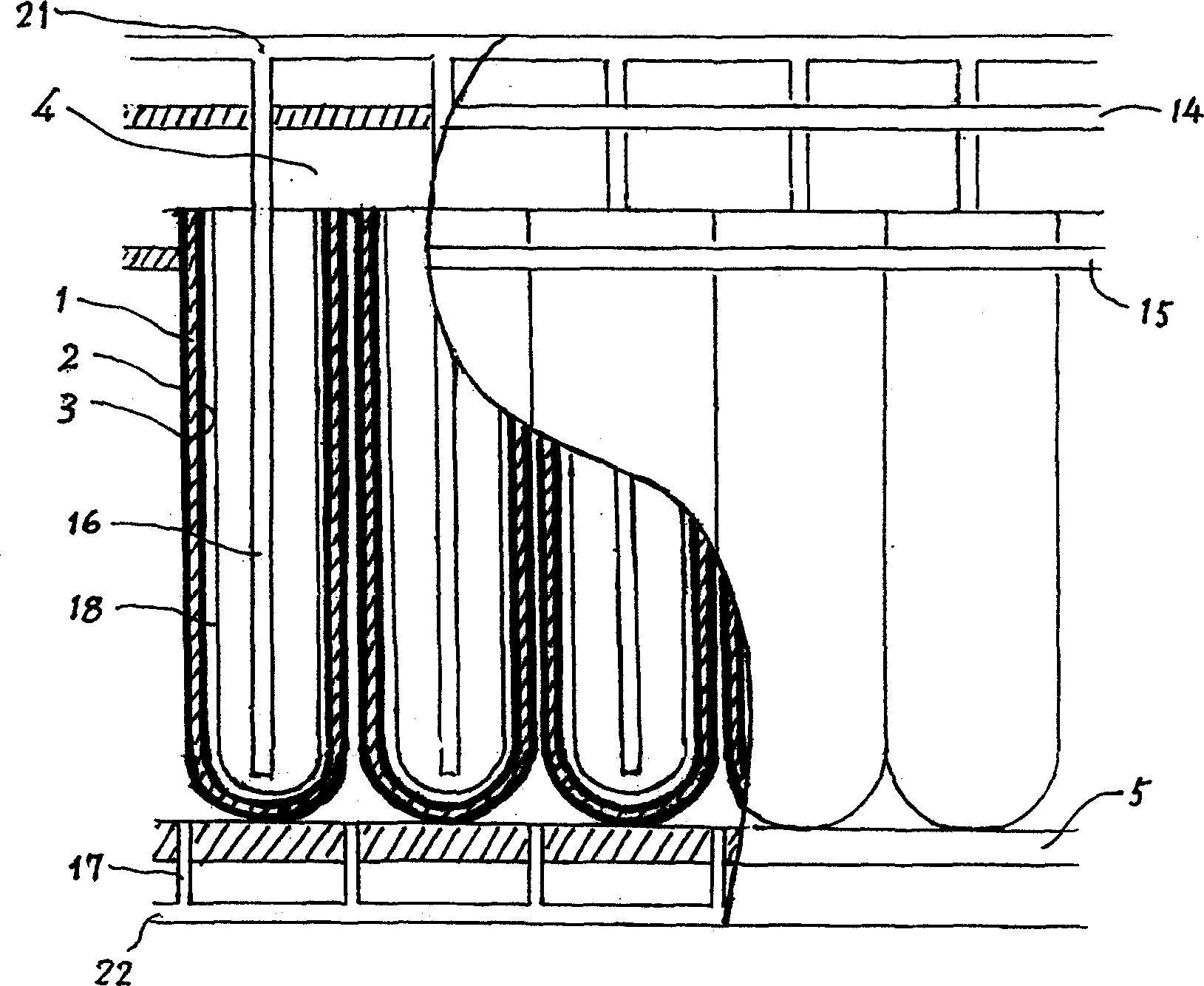
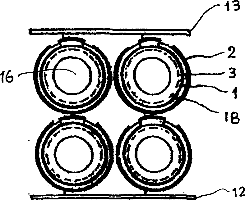
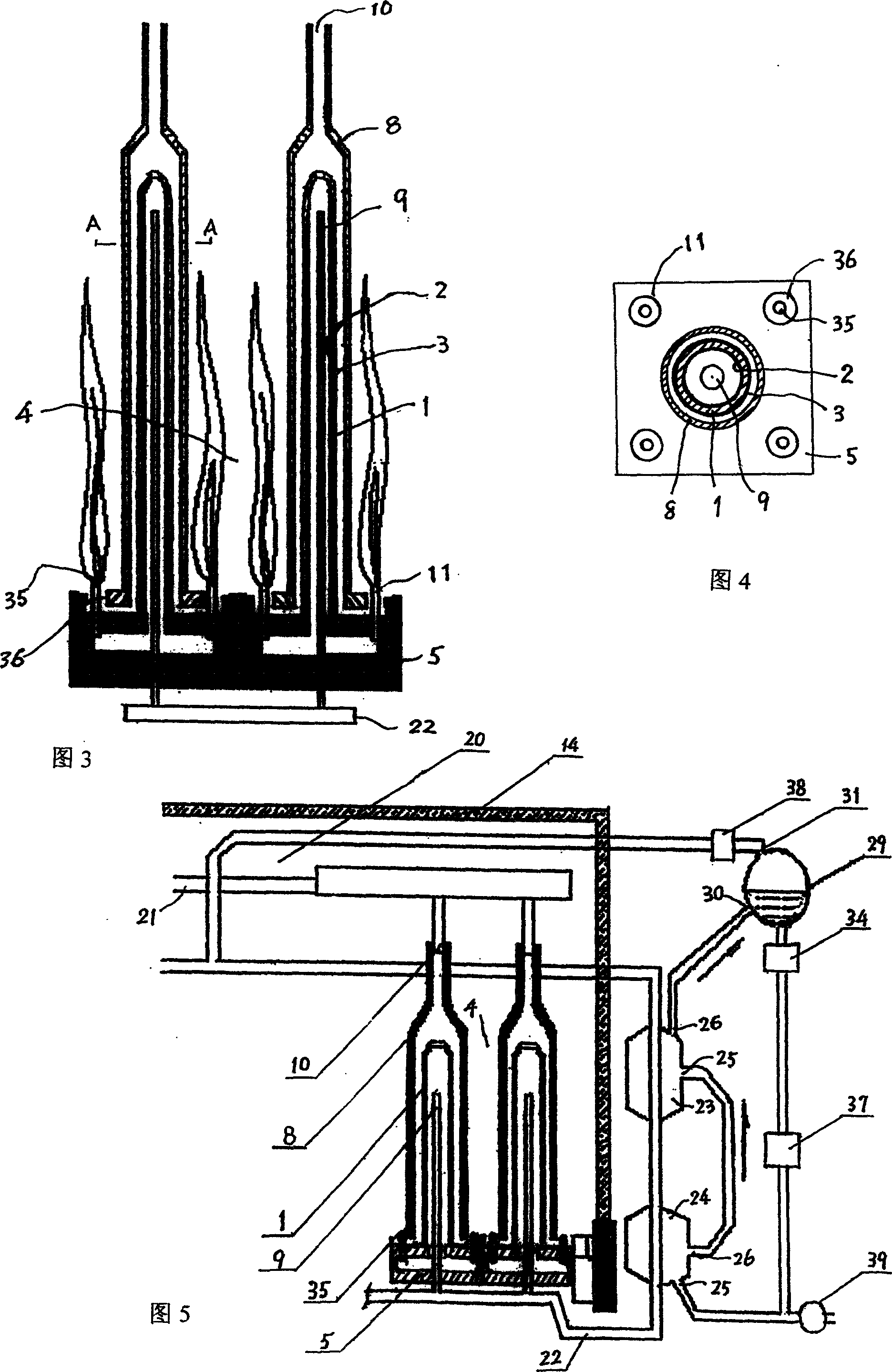
[0024] Fig. 3 shows a schematic cross-sectional view of the structure of a single battery module and adjacent modules. Wherein 1 is an electrolyte tube, and 2 is an anode, which is made on the inner side of the electrolyte tube 1 . 3 is the cathode, which is made on the outside of the electrolyte tube 1. 4 is a combustion chamber, which is the space between the upper top cover 14 and the base 5 of the fuel cell. 5 is a hollow base. 8 is an outer sleeve, and the opening at the upper end of the outer sleeve 8 is an oxidant (air) inflow port 10, and the oxidant (air) inflow port 10 communicates with the oxidant (air) input pipe 21. 9 is a fuel inlet pipe, which passes through the base 5 and communicates with the fuel input pipe 22, and the outside of the outer sleeve 8 is the fuel chamber 4. 11 is the nozzle of the burner, which is composed of a central pipe 35 and an outer ring hole 36. The central pipe 35 ...

Embodiment 2

[0027] Embodiment 2 The indirect internal reforming system of the present invention

[0028]When the fuel is city gas or natural gas, a reforming process is required. Fig. 5 shows a schematic diagram of the overall structure of the fuel cell power generation system including the reforming system. In Fig. 4, the upper half of the fuel chamber 4 is a high-temperature reforming chamber 20, which has an oxidant (air) inlet pipe 21 and a fuel inlet pipe 22, where they are preheated. 23 is a high-temperature converter, and 24 is a low-temperature converter, and they have a water inlet 25 and a water outlet 26 respectively. The fuel inlet pipe 22 passes through them to reform the fuel gas, that is, to convert methane into hydrogen and carbon dioxide, and then enters the electrolyte pipe 1 through the fuel inlet pipe 9 . The water vapor required for fuel reforming is provided by the high temperature converter 23 and recycled. The process is that the water outlet 26 and the gas-water...


PUM


Abstract

The present invention relates to a modular tubular solid oxide fuel cell power generation system, belonging to a power generation equipment. Said invention is formed from the following components: single-cell, combustion chamber, base seat, oxidant (air) input tube and fuel input tube. Said invention also provides the concrete structure of the above-mentioned every component. Said invented structure also includes an indirect internal reforming system, so that it can fully utilize hydrogen gas component of fuel, and can raise stability and performance of cell work.

Description

technical field [0001] The invention belongs to a power generation device, in particular to a power generation system of a solid oxide fuel cell. Background technique [0002] The prior art closest to the present invention is a solid oxide fuel cell (abbreviated as SOFC) power generation system of Westinghouse Corporation of the United States. The structure of the system can be roughly divided into two parts, the upper part is the combustion chamber, and the lower part is the power generation area, that is, the fuel cell body. specific structure reference figure 1 . Each single cell includes an electrolyte tube 1 , which is a circular tubular body with one end open mainly made of yttria-stabilized zirconia material, and supported by a porous support tube 18 inside. A cathode 3 of strontium-doped lanthanum-manganese composite oxide material is sintered on the inner wall of the electrolyte tube 1 , and an anode 2 of nickel cermet material is deposited on the outer side of t...

Claims


Application Information

Patent Timeline
IPC IPC(8): H01M8/1213H01M8/243
CPCY02E60/521Y02E60/50
Inventor 裴力贺天民苏文辉刘江吕喆黄喜强刘晓梅纪媛
Owner JILIN UNIV
Why Eureka
Try Eureka