Impedance circuit of microphone preamplifier

A preamplifier and impedance circuit technology, applied in low frequency amplifiers, impedance networks, electrical components, etc., can solve the problems of insufficient sensitivity of electronic signal response, unfavorable mass production of integrated circuit process, and high dependency of diode process

Inactive Publication Date: 2005-11-02
MERRY ELECTRONICS (SHENZHEN) CO LTD
View PDF0 Cites 2 Cited by
  • Summary
  • Abstract
  • Description
  • Claims
  • Application Information

AI Technical Summary

Problems solved by technology

[0006] However, the process dependencies of the diodes 71 & 72 are high, which is not conducive to the mass production of integr

Method used


Image

  • Impedance circuit of microphone preamplifier
  • Impedance circuit of microphone preamplifier
  • Impedance circuit of microphone preamplifier

Examples


Embodiment Construction

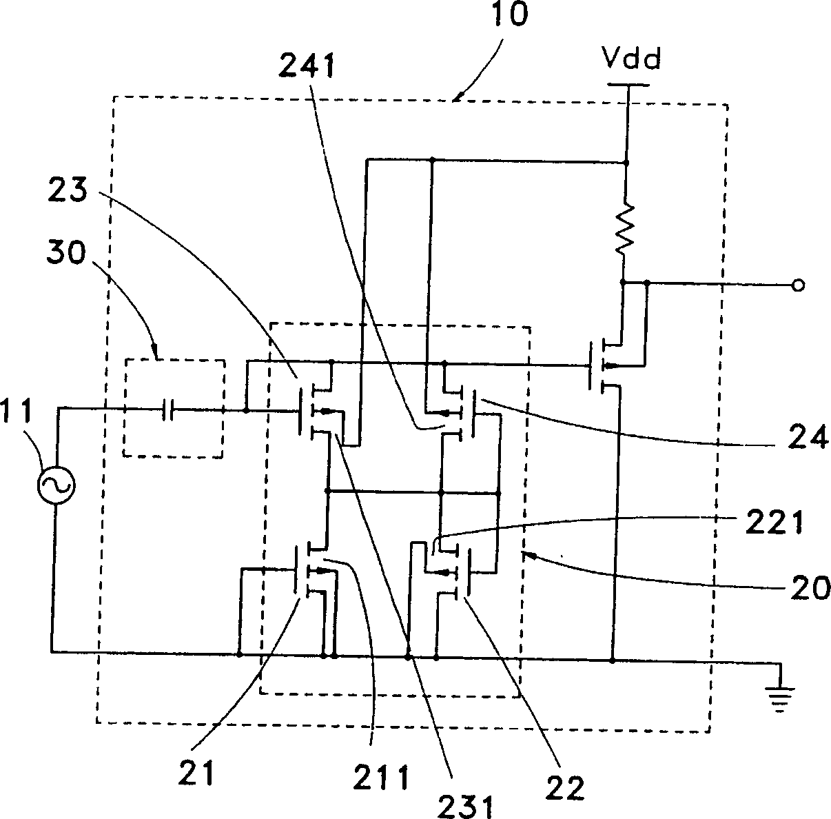
[0025] see image 3 As shown, the present invention provides an impedance circuit 20 of a microphone preamplifier 10, which is connected between a microphone 11 and an amplifier (not shown in the figure), and the impedance circuit 20 includes:

[0026] Two N-type Metal Oxide Half Field Effect Transistors 21 & 22 (N Typc MOSFET), and the P wells 211 & 221 of the two N-type Metal Oxide Half Field Effect Transistors 21 & 22 are grounded GND.

[0027] Two P-type MOSFETs 23 & 24 (P Type MOSFETs), and the N-wells 231 & 241 of the two P-MOSFETs 23 & 24 are connected to a reference voltage Vdd.

[0028] Wherein, the gates and sources of the transistors 21 & 22 & 23 & 24 are connected to achieve a diode-like effect, and the transistors 21 & 22 & 23 & 24 form a bridge circuit.

[0029] In addition, a capacitor 30 is connected between the microphone 11 and the impedance circuit 20 to filter the leakage current generated by the microphone to ensure that the circuit operates at the maximu...


PUM


Abstract

An impedance circuit for microphone head amplifier which set between a microphone and an amplifier to provide higher input impedance and improve the performance of the head amplifier.

Description

technical field [0001] The present invention relates to an impedance circuit of a microphone preamplifier, which is a Complementary Metal-Oxide Semiconductor (CMOS) impedance circuit with relatively high input impedance to improve the performance of the preamplifier circuit. Background technique [0002] A general microphone is used to convert a sound signal into an electronic signal (such as a voltage or current signal), usually the electronic signal is quite weak, so it is impossible to directly connect the microphone to an amplifier, but must be connected between the microphone and the A pre-amplifier is provided between the amplifiers to avoid signal degradation and simultaneously amplify the electronic signal. [0003] see figure 1 As shown, a commonly used preamplifier 1 is arranged between a microphone 4 and an amplifier (not shown), which includes an N-channel Junction Field Effect Transistor 2 (N Channel Junction Field Effect Transistor, NJFET) and a resistor 3, w...

Claims


Application Information

Patent Timeline
IPC IPC(8): H03H7/38
Inventor 王启林黄思伦廖禄立刘瑞彬叶肇宇
Owner MERRY ELECTRONICS (SHENZHEN) CO LTD
Why Eureka
Try Eureka