Composite lead-bearing type external heat insulating wall and its construction method

A construction method and external thermal insulation technology, applied in the direction of thermal insulation, walls, structural elements, etc., can solve the problems of inconvenient pasting operation of polystyrene foam insulation boards, slow construction speed in corner areas, and falling off of wall insulation layers, etc., to achieve easy Wall decoration, convenient construction, and the effect of preventing cracking

Inactive Publication Date: 2005-11-09
朱秦江
View PDF0 Cites 4 Cited by
  • Summary
  • Abstract
  • Description
  • Claims
  • Application Information

AI Technical Summary

Problems solved by technology

[0003] The purpose of the present invention is to provide a composite load-bearing external thermal insulation technology and its construction method, which can solve the problem that the wall insulation layer is prone to fall off, warp, and crack in the existing building thermal insulation wall; it also solves the problem of sticking polystyrene foam insulation board Technical problems of inconvenient operation and slow construction speed in corner areas

Method used


Image

  • Composite lead-bearing type external heat insulating wall and its construction method
  • Composite lead-bearing type external heat insulating wall and its construction method
  • Composite lead-bearing type external heat insulating wall and its construction method

Examples


Embodiment 1

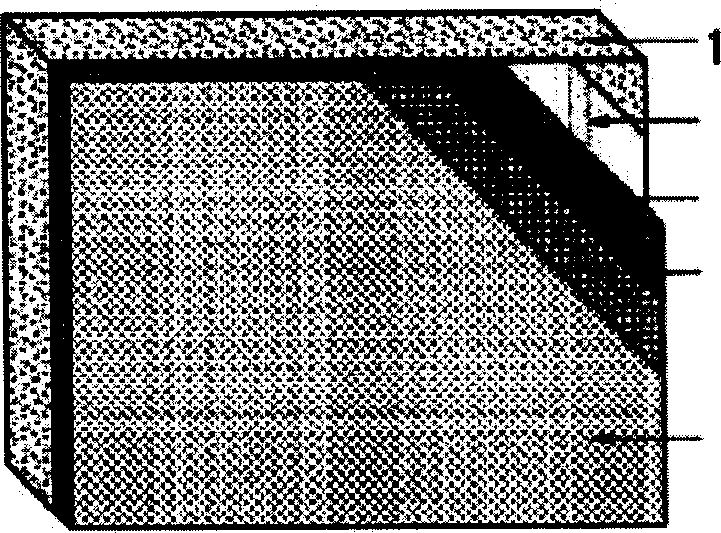
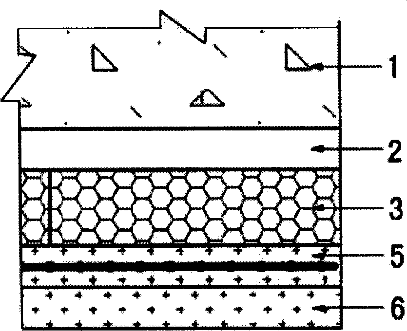
[0041] Embodiment one sees figure 1 , 2 , new building composite load-bearing external thermal insulation wall structure: sequentially fix polymer cement mortar layer 2, light-weight load-bearing thermal insulation wall brick 3, paste glass fiber mesh layer 5 and decorative surface layer 6 on the wall base layer 1 , forming a honeycomb three-dimensional structure of the overall wall.

[0042] see Figure 5 , the above-mentioned lightweight load-bearing thermal insulation exterior wall brick 3 is wrapped with a glass fiber mesh cloth 32 pasted by a polymer cement mortar layer on the outer surface of the polystyrene foam rectangular block 31 .

[0043] The construction method of this composite load-bearing external thermal insulation wall is characterized in that the construction steps are as follows:

[0044] 1), paint a layer of polymer cement mortar layer 2 on the wall base 1;

[0045] 2), laying the light-weight load-bearing thermal insulation wall brick 3, the above-men...

Embodiment 2

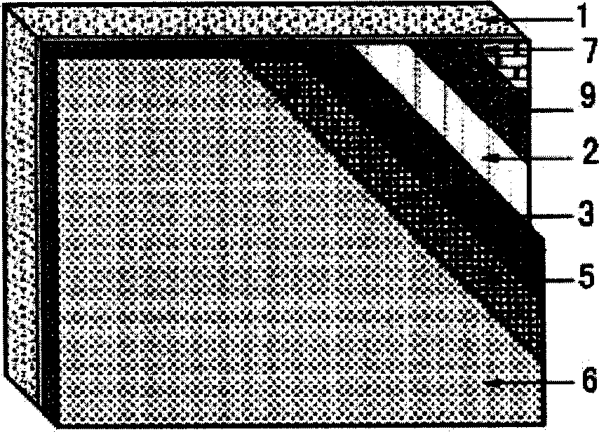
[0050] Embodiment two see image 3 , 4 , the structure of the composite heavy-duty external thermal insulation wall of the old building: On the base layer 1 of the old building wall that has been made with the old surface layer 7, the expanded steel mesh 9, the polymer cement mortar layer 2, and the light-weight heavy-duty thermal insulation wall are fixed in sequence Brick 3 and decorative finish 5. see Figure 5 , the above-mentioned lightweight load-bearing thermal insulation exterior wall brick 3 is made by wrapping a glass fiber mesh cloth 32 pasted by a polymer cement mortar layer on the outer surface of the polystyrene foam rectangular block 31 .

[0051] The construction method of this composite load-bearing external thermal insulation wall is characterized in that the construction steps are as follows:

[0052] 1), the old surface layer 7 has been made on the wall base 1, and the steel mesh 9 is laid on the surface of this old building, and it is fixed with rivets ...


PUM


Abstract

This invention discloses a composite load-bearing type external heat insulating wall, light weight load-bearing type heat insulating wall brick is pasted on wall. The wall brick is that polystyrene foam plastic rectangular block external surface is enwrapped by a layer of glass fiber grid fibric pasted by polymer cement sand bed, decorating layer is pasted on its surface. steel wire mesh is needed to fixed on wall face of old building. Building wall heat insulating and load-bearing effect are revealed in this invention, the advantages are good and precise flatness, high bond strength, wall crack and drop-out can be effectively prevented, it is easy to be made for multiple wall decorating. This invention is propitious to building energy saving and loss reduction, it ca be used to all kinds of new built concrete heat protection wall body, and heat insulating and modification to old buildings.

Description

(1) Technical field [0001] The invention relates to a thermal insulation wall body of a building and a construction method thereof. (2) Background technology [0002] In today's energy shortage, the energy saving and consumption reduction of buildings is more important. The existing building insulation wall and its construction method is to paste polystyrene foam insulation board on the concrete base, because polystyrene foam (EPS) has poor impact resistance, it is quite different from inorganic materials, and the insulation The board is not easy to stick firmly, and the wall insulation layer often falls off, warps, and cracks, which greatly affects the construction quality. On the other hand, a polystyrene foam insulation board has a relatively large area, which is inconvenient during construction and requires the cooperation of multiple people. Every corner area must be measured and cut, which slows down the construction speed. (3) Contents of the invention [0003] T...

Claims


Application Information

Patent Timeline
Patent Type & Authority Applications(China)
IPC IPC(8): E04B2/00
Inventor 朱秦江
Owner 朱秦江
Why Eureka
Try Eureka