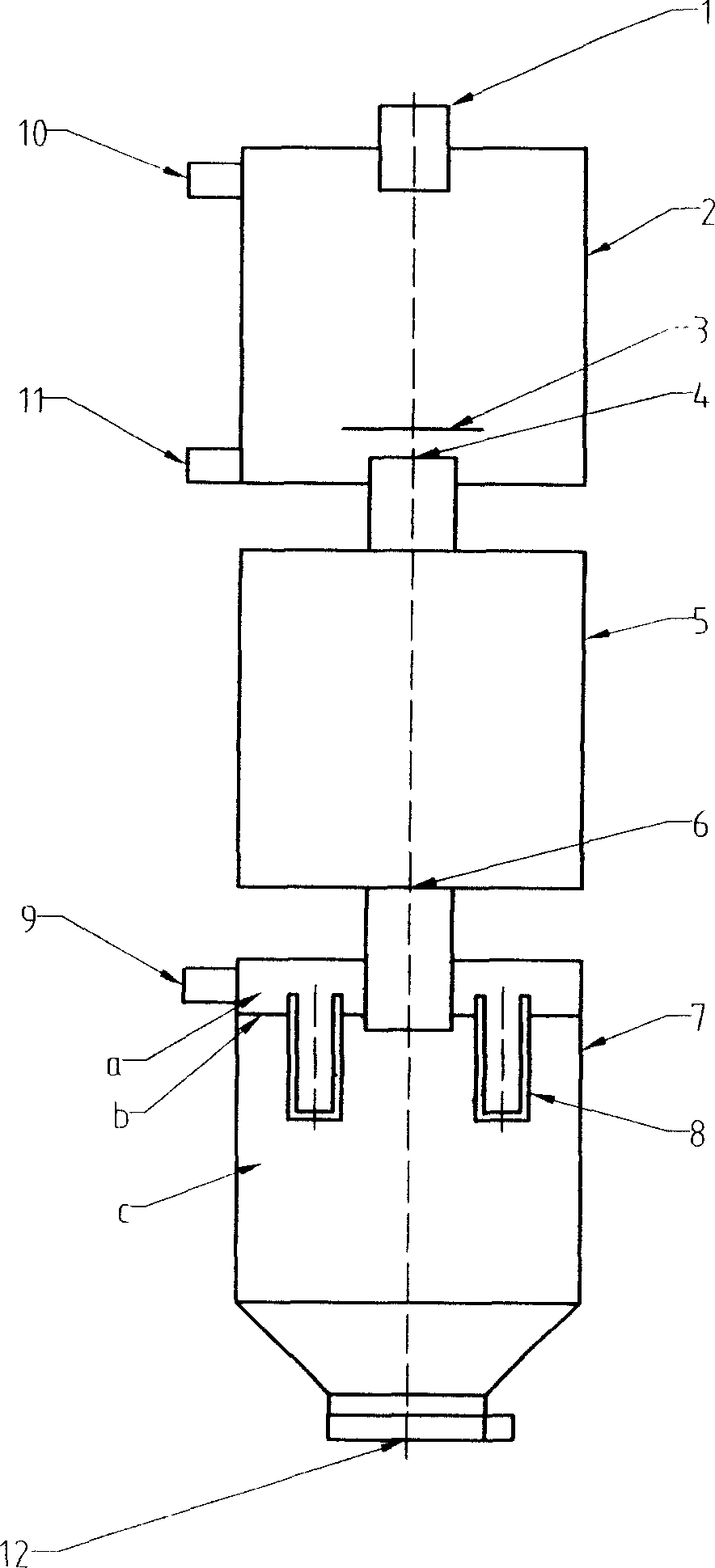
Microwave spray drier
A drying and heating drying technology, applied in the field of spray drying and microwave, to achieve the effect of improving thermal efficiency, small equipment volume, and reducing the possibility of material pollution
- Summary
- Abstract
- Description
- Claims
- Application Information
AI Technical Summary
Problems solved by technology
Method used
Image

Examples
Embodiment Construction
[0020] Group No. 1: Liquid (solution, mixed solution, suspension, emulsion, slurry) concentration: about 60% (w / w);
[0021] Particle size range after atomization: less than about 2000μm;
[0022] The particle size range of mist droplets entering the heating and drying chamber: less than about 100 μm;
[0023] Effective microwave electric field strength in heating and drying chamber: about 500 kV / m;
[0024] Heat radiation intensity in heating and drying room: more than 10 kW / square meter
[0025] Heating and drying time: about 0.1 seconds;
[0026] Carrier fluid: air;
[0027] Working pressure in heating and drying chamber: about 0.2MPa (absolute pressure);
[0028] Group
No
liquid thick
Spend
Heating and drying indoor pellets
Electric field strength
(kV / m)
(Second)
carrier stream
body
definitely work
pressure
(MPa)
2
aro...
PUM
 Abstract
Description
Claims
Application Information
 - R&D
- Intellectual Property
- Life Sciences
- Materials
- Tech Scout
- Unparalleled Data Quality
- Higher Quality Content
- 60% Fewer Hallucinations
Browse by: Latest US Patents, China's latest patents, Technical Efficacy Thesaurus, Application Domain, Technology Topic, Popular Technical Reports.
© 2025 PatSnap. All rights reserved.Legal|Privacy policy|Modern Slavery Act Transparency Statement|Sitemap|About US| Contact US: help@patsnap.com