Laser color display device possessing three primary colors of red, green and blue

A color display and tri-primary color technology, applied in lasers, laser parts, semiconductor lasers, etc., can solve the problem of not bright enough colors, and achieve the effect of bright colors, rich colors, and extended color gamut

Inactive Publication Date: 2006-01-18
INST OF PHYSICS - CHINESE ACAD OF SCI
View PDF1 Cites 26 Cited by
  • Summary
  • Abstract
  • Description
  • Claims
  • Application Information

AI Technical Summary

Problems solved by technology

[0003] At present, there are many reports on laser display, using different technical routes to obtain three-primary-color lasers, and the three-primary-color wavelengths used are also different, such as: 2001 SPIE magazine volume 4362 pages 203-212, reporting on Q-Peak in the United States The three-color laser for laser display developed by the company adopts LD pumping Nd:YLF oscillation-amplification structure to generate high-power 1047nm laser, then frequency doubles to obtain high-power 524nm green light, and then pumps LBO OPO to generate 898nm signal light and 1256nm idler light, signal light and idler light are frequency multiplied t

Method used


Image

  • Laser color display device possessing three primary colors of red, green and blue
  • Laser color display device possessing three primary colors of red, green and blue
  • Laser color display device possessing three primary colors of red, green and blue

Examples


Embodiment 1

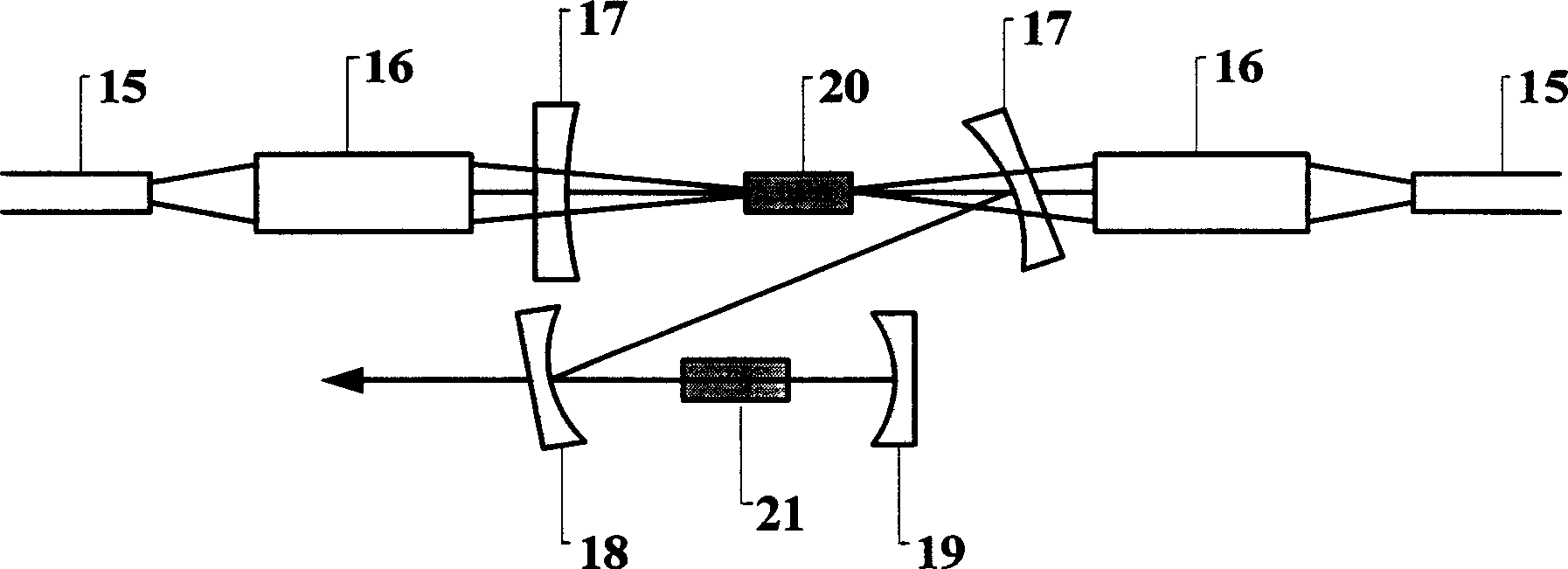
[0044] according to image 3 The optical path to make a 671 / 660nm red laser

[0045] The laser crystal 20 uses Nd:YV04 or Nd:YAG crystal, on which an optical film is coated, the coating parameters are HT@808nm&1342nm or HT@808nm&1319nm, the pump light source 15 adopts an 808nm semiconductor laser LD, and a coupling system 16 is set on the optical path in front of the pump light source 15 1. A resonant cavity made of a pair of resonant cavity mirrors 17, 18 and 19 resonant cavity mirrors. The laser crystal 20 is placed in the middle of the pair of resonant cavity mirrors 17. A non- A linear optical crystal 21 ; a coupling system 16 and a pump light source 15 are placed on the output optical path of the cavity mirror 17 .

[0046] After the pumping light is pumped by the coupling system 16, the fluorescence of 1342nm or 1319nm is generated. By adjusting the cavity mirrors 17, 18, 19, the fluorescence of 1342nm or 1319nm is oscillated to generate laser light. The nonlinear optical...

Embodiment 2

[0056] according to Figure 4 Make a side-pumped 660nm red laser with the optical path

[0057] The laser crystal 20 uses Nd:YAG rods, and the two transparent surfaces are coated with 1319nm anti-reflection film; the pump light 15 adopts a multi-dimensional 808nm semiconductor laser array and places it around the laser crystal 20 according to a certain shape and position. The components formed in this way are called One laser head, only one laser head can be used in the optical path, and multiple laser heads can also be used in series. When two laser heads are used in series, a 90-degree optical rotation plate 23 is inserted between them to compensate for thermally induced birefringence. A composite resonant cavity composed of a pair of resonant cavity mirrors 17, 18 and 19 is arranged sequentially on the optical paths on both sides of the head, and a nonlinear optical crystal 21 is placed between the resonant cavity mirror 18 and the resonant cavity mirror 19; The two laser ...


PUM

PropertyMeasurementUnit
Thicknessaaaaaaaaaa

Abstract

The invention relates to a red, green and blue three primary colors laser color display device, which comprises red laser, green laser and blue laser, wherein three coherent blanking device are corresponding positioned on the output optical path; first reflecting mirror, liquid crystal optical valve, beam cementing prism are positioned on the red output optical path after beam coherent blanking; second liquid crystal optical valve, beam cementing prism are positioned on the green output optical path after beam coherent blanking; a reflecting mirror is positioned on the optical path of blue laser; third liquid crystal valve id positioned between reflecting mirror and beam cementing prism; projection lens system is positioned on the optical path of output light after beam cementing prism.

Description

technical field [0001] The invention relates to a laser display device, in particular to a laser color display device with three primary colors of red, green and blue. Background technique [0002] Since the laser is a line spectrum, it has a higher color saturation than the phosphor, and the displayed color can be made more vivid by selecting the three primary color wavelengths close to the vertex angle of the chromaticity triangle. At the same time, it can also make the formed chromaticity triangle area larger, showing more real and richer colors in nature. Therefore, laser display is one of the major development directions of high-end display technology, and has attracted great attention from the international community. [0003] At present, there are many reports on laser display, using different technical routes to obtain three-primary-color lasers, and the three-primary-color wavelengths used are also different, such as: 2001 SPIE magazine volume 4362 pages 203-212, re...

Claims


Application Information

Patent Timeline
IPC IPC(8): G02F1/35H01S5/00G02B27/18
Inventor 许祖彦侯玮李瑞宁林学春姚爱云王桂玲张瑛毕勇孙志培张鸿博崔大复徐贵昌
Owner INST OF PHYSICS - CHINESE ACAD OF SCI
Why Eureka
Try Eureka