Improved ion gun

An ion gun and an improved technology, applied in the field of ion guns, can solve the problems of reducing the effective area of ​​deposition, reducing the yield of peripheral filters, and reducing production capacity, and achieving the effect of improving production capacity and production yield.

Inactive Publication Date: 2006-01-25
ASIA OPTICAL CO INC
View PDF4 Cites 9 Cited by
  • Summary
  • Abstract
  • Description
  • Claims
  • Application Information

AI Technical Summary

Problems solved by technology

In terms of the entire substrate 70, although such an ion beam jet covers the entire area of ​​the substrate 70, the energy cannot be concentrated, which will lead to a decrease in the yield of the peripheral optical filter, or reduce the effective area of ​​deposition, will eventually reduce productivity

Method used


Image

  • Improved ion gun
  • Improved ion gun
  • Improved ion gun

Examples


Embodiment Construction

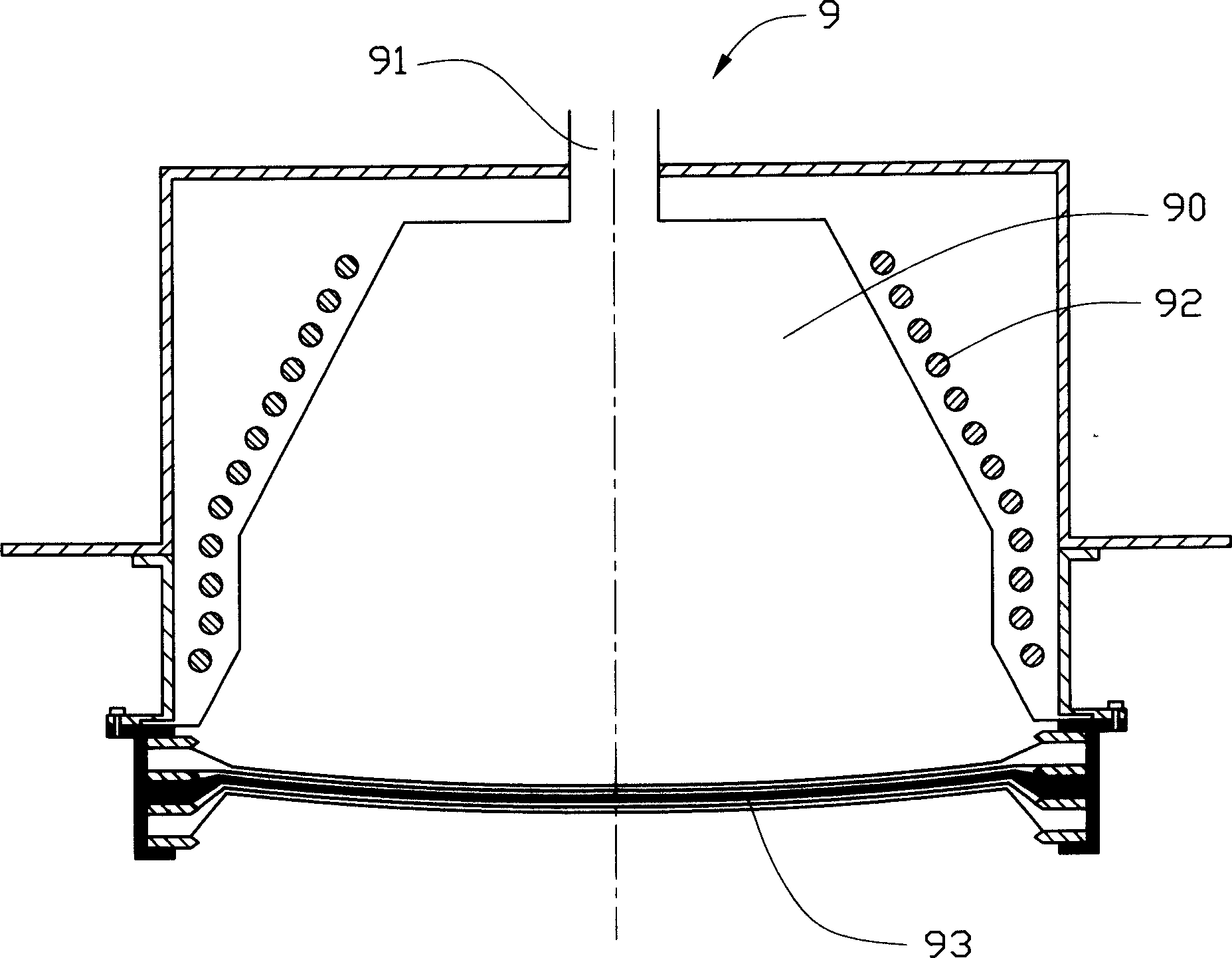
[0020] Please also see Figure 4 and Figure 5 , the main components of the improved ion gun 1 of the present invention are similar to existing products, and it is equipped in the coating chamber 100 (which can be a vacuum chamber) and is applied to the ion-assisted deposition process for manufacturing optical thin films. The ion gun 1 mainly includes a discharge Chamber (plasma chamber) 10, a gas source for supplying the gas to be ionized, an exciter located at the side of the discharge chamber, an ion beam extraction device installed at the opening of the discharge chamber, and a peripheral device located at the periphery of the discharge chamber and the exciter Shield 30 . Wherein, the discharge chamber 10 is made of non-conductive material, the shielding member 30 may be a metal member, and the exciter may be a radio frequency coil to generate a high frequency electromagnetic field to ionize the gas to generate plasma.

[0021] The above-mentioned ion beam extraction dev...


PUM


Abstract

This invention discloses a reformed ion gun including a discharge chamber, a gas source, an exciter, a grid component and a screen component, among which, the grid component includes a screen grid acceleration grid and a stop grid, the screen grid belongs to the anode and closes to the ionized ions, the acceleration grid belongs to the cathode and inter leaved with the screen grid, the stop grid belongs to the earth grid above the acceleration grid, the central zone of each grid has a curved surface, several aligned punches are set on these curved surfaces to form an extraction channel for ion beams, the curved grid surface is in a concave state and the angle of the ion beam led out from said grid components is in collection state so as to get qualified optical films.

Description

【Technical field】 [0001] The invention relates to an improved ion gun, especially an ion gun with a special grid component and applied in the manufacturing process of optical thin films. 【Background technique】 [0002] At present, the application of optical thin film plays an important role in high-tech products such as laser optics and optical fiber communication. It coats the surface of various optical materials with one or more layers of film, and uses the interference effect of light to change the transmitted light or reflected light. The polarization, phase and energy of the film can be coated on crystals, plastics, optical glass and other materials. The most commonly used substrate is optical glass. The thickness of the film can range from a few nm to several μm, and the number of layers can range from one layer to hundreds of layers. Optical filters are one of the types of optical thin film applications, which are made by plating multiple layers of metal or dielectric...

Claims


Application Information

Patent Timeline
Patent Type & Authority Applications(China)
IPC IPC(8): H01J27/02H01J27/14H01J37/08H01J33/02F03H1/00
Inventor 张陈益升
Owner ASIA OPTICAL CO INC
Why Eureka
Try Eureka