
Method and system for desulfurization in wet-process of limestone-gypsum, and resource process of desulfurized gypsum

A technology for wet desulfurization and desulfurization gypsum, which is applied in the field of limestone-gypsum wet desulfurization and desulfurization gypsum resource treatment and systems, can solve the problems of desulfurization by-product treatment, environmental pressure, remote pollution and other problems, and reduce the cost of re-dehydration , the effect of reducing pollution pressure and project cost

Inactive Publication Date: 2006-02-01
万炳进
View PDF0 Cites 14 Cited by
  • Summary
  • Abstract
  • Description
  • Claims
  • Application Information

AI Technical Summary

Problems solved by technology

[0007] (1) SO 2 In order to store the water-containing desulfurized gypsum discharged for a period of time, the production enterprise must build a desulfurized gypsum storage. The volume of the general desulfurized gypsum storage is several thousand cubic meters. In order to adapt to it, the vacuum belt dehydration machine in the wet desulfurization system must There is a higher installation height, which will cause higher pressure on engineering investment for enterprises
[0008] (2) Since the desulfurization gypsum resource treatment process of off-site dehydration needs heat source, so the off-site treatment needs to build a heat source facility in addition to the new factory building, which not only increases the project investment, but also consumes more energy during the treatment process. It will increase the treatment cost and management cost of desulfurization gypsum. In addition, if a small boiler is used, it will cause off-site pollution.
[0009] (3) Some small gypsum users do not have this ability due to this off-site treatment method, which limits the application of desulfurized gypsum resources to a certain extent, and also makes these SO 2 The disposal of desulfurization by-products of enterprises has become a problem, which has also caused environmental pressure
These high-temperature exhaust gases (or steam) emit heat to the environment, which will also cause thermal pollution to the environment.
[0011] (5) There is also the possibility of causing secondary environmental pollution during the transportation process from the desulfurization gypsum production enterprise to the gypsum user and in the re-dehydration process

Method used


Image

  • Method and system for desulfurization in wet-process of limestone-gypsum, and resource process of desulfurized gypsum
  • Method and system for desulfurization in wet-process of limestone-gypsum, and resource process of desulfurized gypsum
  • Method and system for desulfurization in wet-process of limestone-gypsum, and resource process of desulfurized gypsum

Examples


Embodiment 1

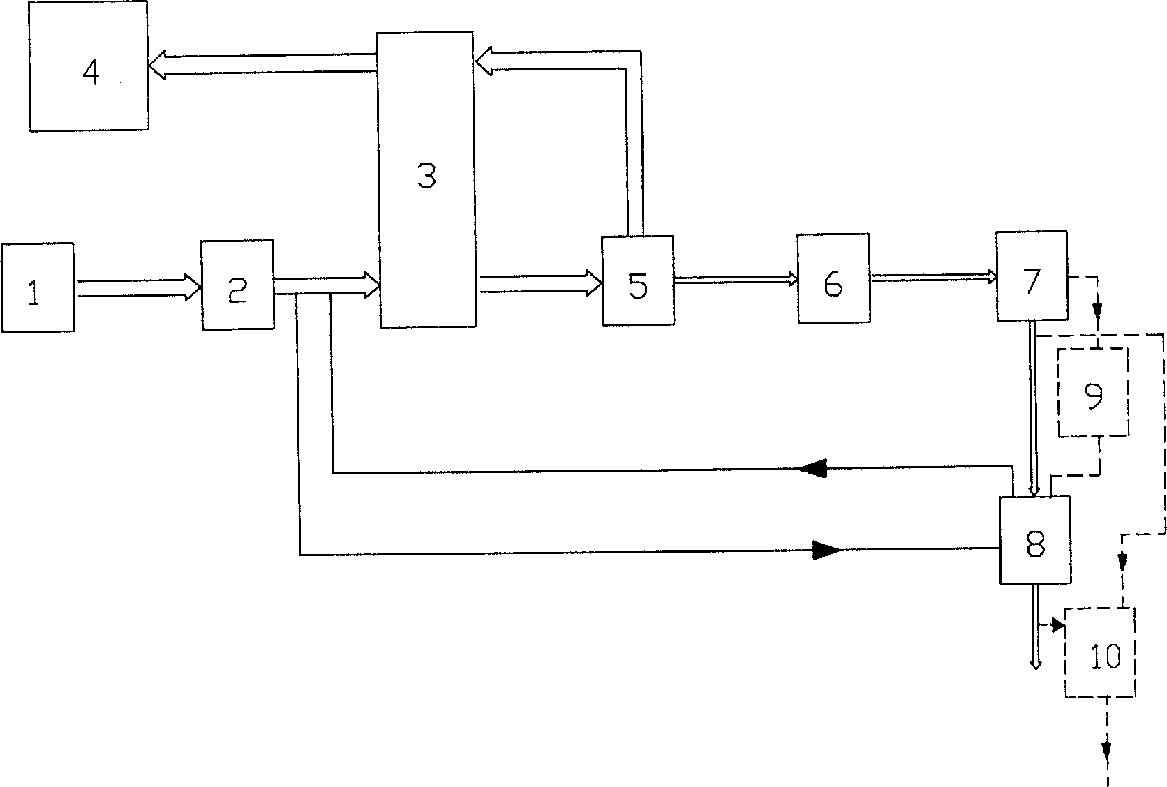
[0036] Such as figure 2 Shown is a process flow diagram of a limestone-gypsum wet desulfurization and desulfurization gypsum resource treatment system. The system includes a coal-fired boiler 1, a limestone-gypsum wet desulfurization system and a desulfurized gypsum resource treatment system. Limestone-gypsum wet desulfurization system includes desulfurization increasing fan 2, flue gas heat exchanger 3, chimney 4, absorption tower 5, hydrodynamic gypsum slurry cyclone 6 and vacuum belt dehydrator 7. The sulfur-containing flue gas with a temperature of 120-150°C in the boiler 1 is pressurized by the desulfurization booster fan 2 and cooled by the flue gas heat exchanger 3, then enters the absorption tower 5, and reacts with the calcium-based absorbent under forced oxidation conditions Calcium sulfate dihydrate is generated to achieve the purpose of flue gas desulfurization. The flue gas after desulfurization is heated by the flue gas heat exchanger 3 and then discharged into...

Embodiment 2

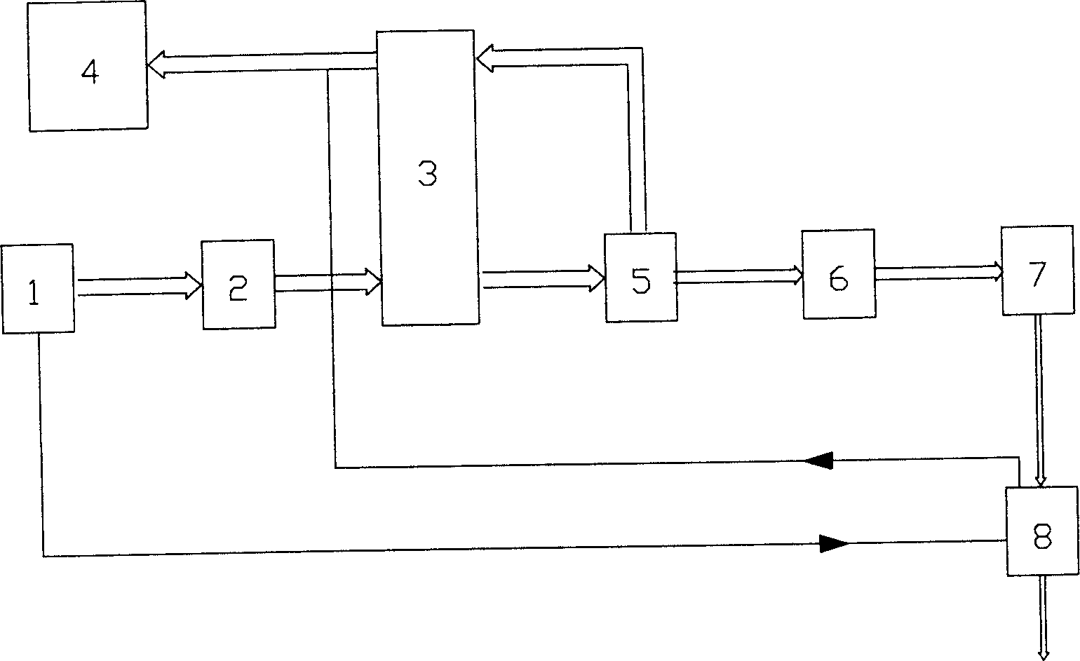
[0041] Such as image 3 As shown, this embodiment is aimed at a process flow for producing anhydrite products. The limestone-gypsum wet desulfurization system in this embodiment is the same as that in Embodiment 1, including desulfurization increasing fan 2, flue gas heat exchanger 3, chimney 4, absorption tower 5, hydrodynamic gypsum slurry cyclone 6 and vacuum belt dehydrator 7. The main equipment of the desulfurization gypsum resource processing system is also the drying calciner 8, the difference is that the hot air with a preheated temperature of about 320°C from the air preheater in the boiler 1 is used as the dehydration drying During the process, the heat source of the calciner 8 is dried, and the powdered desulfurized gypsum is dried and calcined after being adjusted by the electric heater or the temperature of the cold air outlet to remove free water and all bound water to obtain anhydrous gypsum products. The hot air after use is then directly discharged into the ...

Embodiment 3

[0045] Such as Figure 4 As shown, this embodiment is aimed at a process flow for producing α hemihydrate gypsum products. The limestone-gypsum wet desulfurization system in this embodiment is the same as that in Embodiment 1, including desulfurization increasing fan 2, flue gas heat exchanger 3, chimney 4, absorption tower 5, hydrodynamic gypsum slurry cyclone 6 and vacuum belt dehydrator 7. The main equipment of the desulfurization gypsum resource treatment system is also the drying calciner 8, the difference is that an autoclave 11 is also provided at the upstream position of the drying calciner 9 process, and the heat source required by the autoclave 11 is generated by the boiler 1 0.3Mpa saturated steam, and the heat source used by the drying calciner is the flue gas with a temperature of 120-150°C after the desulfurization booster 2 is supercharged and before the flue gas heat exchanger cools down.

[0046] According to the characteristics of the production of α hemihy...


PUM


Abstract

A process and system for desulfurizing the fume by wet lime stone-gypsum method is disclosed. The used dosulfurizing gypsum can be reclaimed through dewatered by the afterheat of boiler to obtain the bihydrated gypsum used as the setting retarder of cement or the semi-hydrated or anhydrated gypsum used for building purpose.

Description

technical field [0001] The present invention relates to resource regeneration of flue gas desulfurization and desulfurized by-product desulfurized gypsum, which combines desulfurized gypsum resource treatment technology, energy-saving technology and wet flue gas desulfurization (FGD) process to realize wet flue gas desulfurization system and desulfurized gypsum The integration of resource treatment process is a further extension and improvement of the gypsum dehydration system in the wet flue gas desulfurization process, so as to achieve the effect of direct use and resource application of the by-product of wet flue gas desulfurization - desulfurization gypsum, and to develop circular economy . Background technique [0002] Boilers or reaction furnaces used in power plants, thermal power plants, or other industrial enterprises use coal as energy source. During the production process, coal combustion produces harmful flue gas containing sulfur, mainly SO 2 . At present, man...

Claims


Application Information

Patent Timeline
IPC IPC(8): C04B11/02
Inventor 万炳进
Owner 万炳进
Learn More