
Automatic gain control system with self-adaptive climb and decay time

A gain control, control signal technology, applied in gain control, amplification control, electrical components, etc., can solve problems such as precise control difficulties, current consumption, changes, etc.

Active Publication Date: 2006-02-15
SHENZHEN STS MICROELECTRONICS
View PDF0 Cites 8 Cited by
  • Summary
  • Abstract
  • Description
  • Claims
  • Application Information

AI Technical Summary

Problems solved by technology

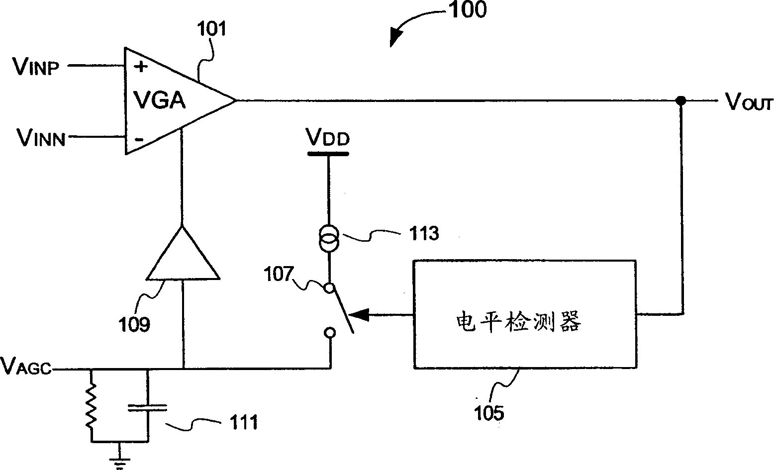
While this has the advantage of simplicity, the rate of current flowing through the resistor changes continuously depending on the voltage across the capacitor
In addition, when a current is applied through the switch 107, a part of the current is consumed by the resistor
As a result, V AGC changes in a non-linear fashion, making precise control more difficult

Method used


Image

  • Automatic gain control system with self-adaptive climb and decay time
  • Automatic gain control system with self-adaptive climb and decay time
  • Automatic gain control system with self-adaptive climb and decay time

Examples


Embodiment Construction

[0016] The invention is illustrated and described in terms of a specific circuit implementation of automatic gain control. Although the invention will typically be implemented as part of an integrated circuit (IC), it is contemplated that the invention can be implemented as discrete components, as a stand-alone IC, or as part of a system-on-a-chip (SOC) or multi-chip system.

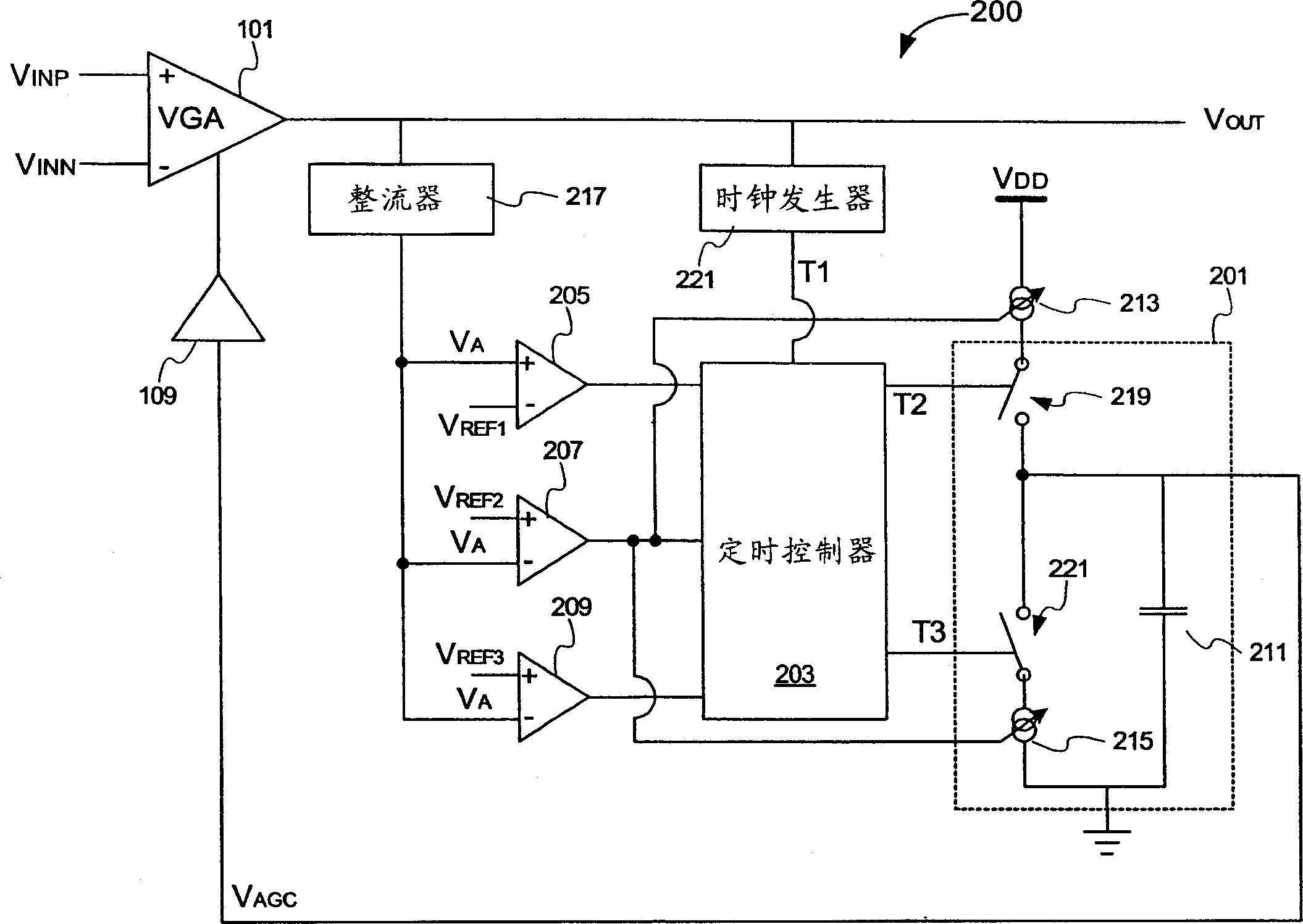
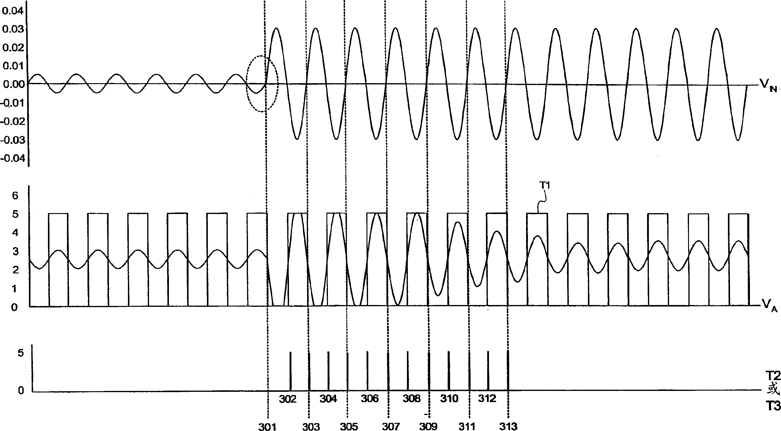
[0017] figure 2 An exemplary implementation is illustrated in which the AGC control voltage (V AGC ), the charge pump is driven by the timing controller 203. Clock generator 221 generates a V OUT The frequency of the signal is synchronized with the clock pulse T1. The charge pump 201 charges the capacitor 211 by applying the pulse T2 and discharges the capacitor 211 by applying the pulse T3. Generally, the working time of the charge pump 201 is relatively short, so the capacitor 211 can be small compared with the capacitor 111 shown in FIG. 1 . This allows capacitor 211 to be implemented as an integ...


PUM


Abstract

The gain control method uses variable gain amplifier to amplify input signal and generate output signal. Wherein, it selects the gain based on the control signal on control input terminal of the said amplifier; when the output signal is larger than the upper boundary, the change of increment controls signal amplitude and decrease the amplifier's gain; or else, the change of increment controls the signal amplitude to increase the amplifier's gain by stepping linear way.

Description

technical field [0001] The present invention relates generally to control systems and, in particular, to circuits, systems and methods for providing automatic gain control with adaptive attack and decay times. Background technique [0002] Automatic gain control (AGC) circuits are common components in a wide variety of analog and digital systems. For example, when reading a signal from the disc surface, the signal amplitude generated by the read head may vary significantly and benefit from automatic gain control to scale the signal amplitude before further processing the signal. In communication systems, receivers, tuners, and demodulators often require AGC processing of received signals in order to account for variations in the received channel. The AGC circuit is also used to prevent saturation in the analog-to-digital converter. Other applications of AGC circuits are known. AGC circuits attempt to maintain a relatively constant output signal amplitude over a range of s...

Claims


Application Information

Patent Timeline
Patent Type & Authority Applications(China)
IPC IPC(8): H03G3/20
CPCH03G3/3036H03G3/30
Inventor 杨芳黄勍隆
Owner SHENZHEN STS MICROELECTRONICS
Learn More