Heating apparatus

A heating device and heated technology, applied in the direction of electric heating plate heating arrangements, optics, instruments, etc., can solve problems such as uneven drying, achieve uniformity, achieve film thickness, and suppress temperature rise

Inactive Publication Date: 2006-03-08
NISSHA PRINTING COMPANY
View PDF1 Cites 19 Cited by
  • Summary
  • Abstract
  • Description
  • Claims
  • Application Information

AI Technical Summary

Problems solved by technology

[0010] In addition, not only the size of the above-mentioned liquid crystal panel is required, but also its performance is also pursued. Therefore, how to eliminate the small drying unevenness that has been a problem in the past has become a problem.
[0011] Indeed, the effect of disposing a plastic material with low thermal conductivity on the front ends of the lift pin 505 and the proximity pin 511 is very obvious, but the above-mentioned slight drying unevenness can be recognized, so as a countermeasure, the above-mentioned measures cannot be used. Said to be very complete
[0012] Moreover, even when such a heating device structure is adopted, it is powerless against the high-temperature updraft rising from the through-hole of the heating plate, which becomes a main cause of uneven drying.

Method used


Image

  • Heating apparatus
  • Heating apparatus
  • Heating apparatus

Examples


Embodiment 1

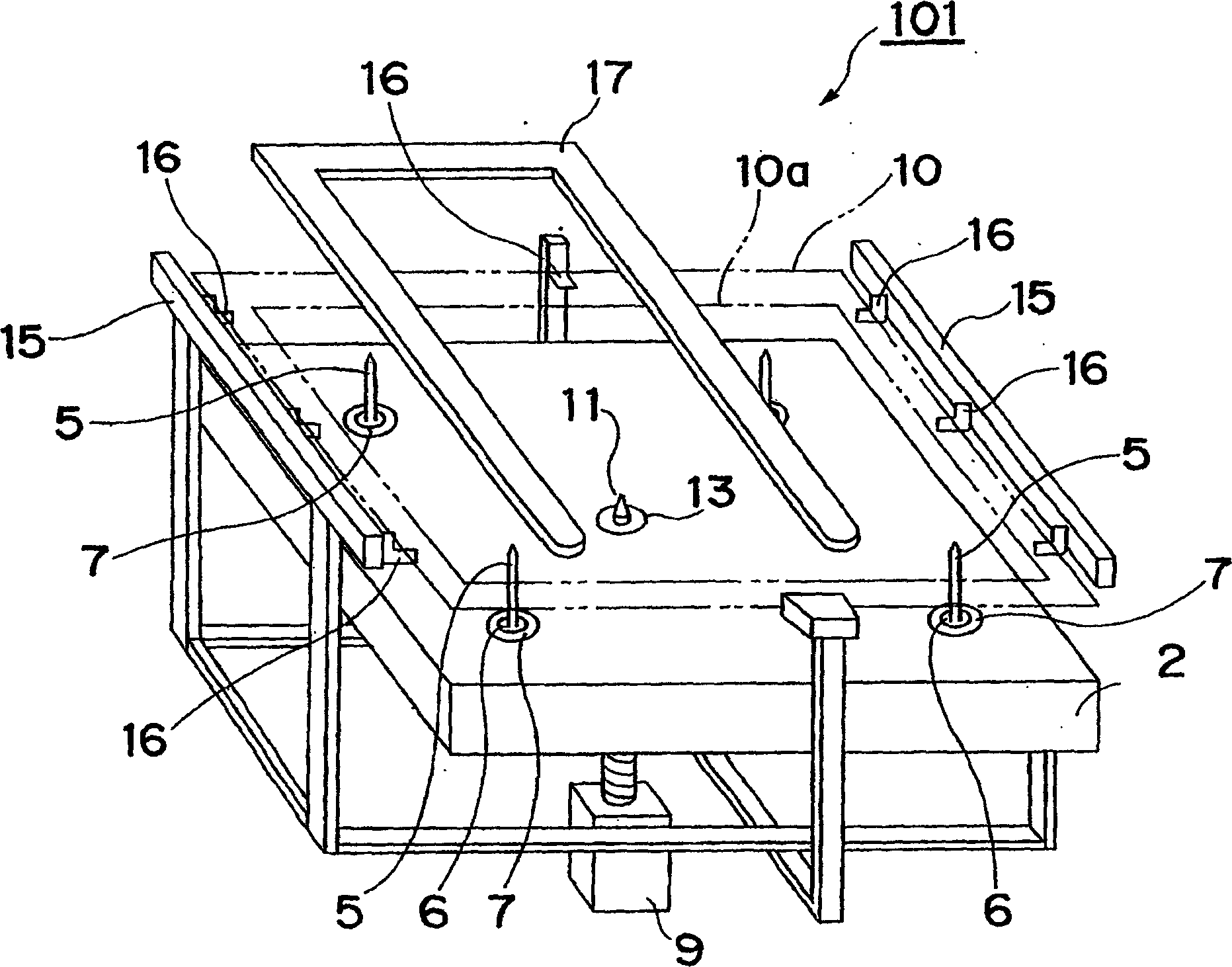
[0134] Next, an example of the approach pin 11 and the temperature adjusting member 13 used in the heating device 101 of the above-mentioned embodiment will be described as Example 1 below.

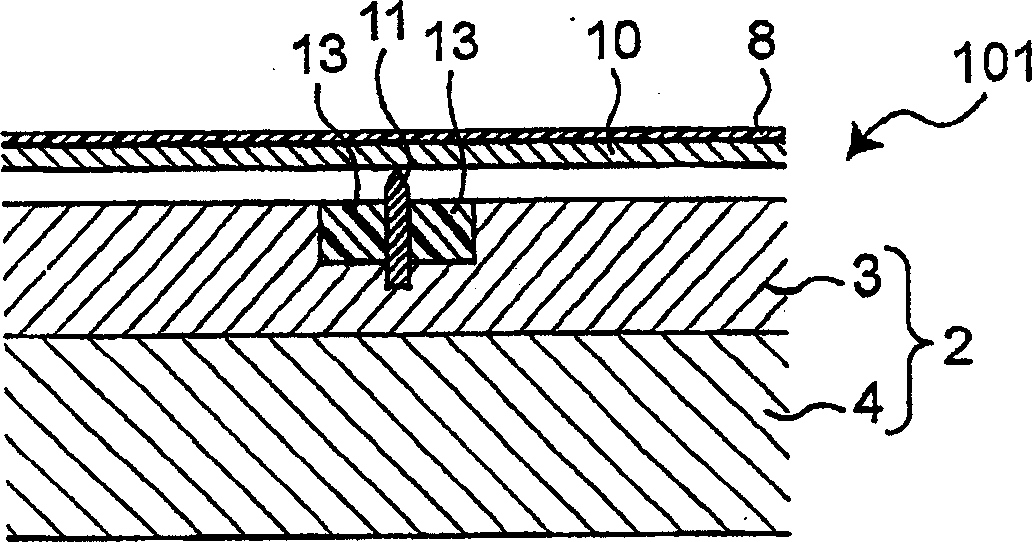
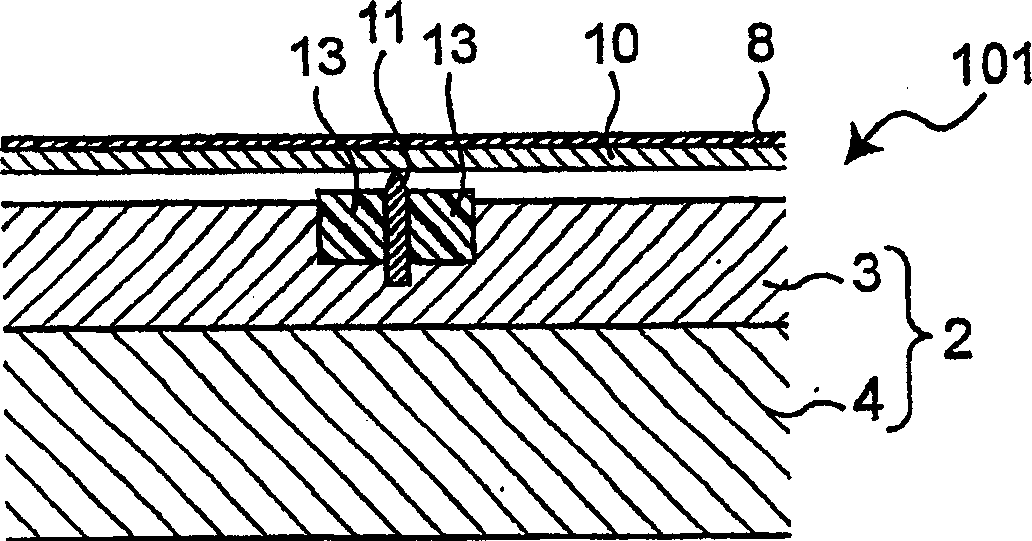
[0135] In this Example 1, the image 3 The structure of the heating device 101 shown in the schematic cross-sectional view of . Specifically, as image 3 As shown, the heating plate 2 is composed of a 10 mm thick aluminum top plate portion 3 and a heat generating portion 4 . In addition, as the approach pin 11, a tip made of Ultem (registered trademark: ULTEM: polyetherimide) and having a diameter of 3 mm was used. In addition, as the temperature adjustment member 13, a ring made of Ulutem (registered trademark) with an outer diameter of 10 mm and a thickness of 10 mm is used. below.

[0136] In addition, the substrate 10 is made of soda lime glass with a thickness of 0.7 mm. In addition, as the film raw material solution 8, that is, the coating material, an ink for liquid crystal al...

Embodiment 2

[0143] Next, an example of the lift pin 5 and the temperature adjustment member 7 used in the heating device 101 of the above-mentioned embodiment will be described as Example 2 below.

[0144] In this second embodiment, various means in the description of the above-mentioned embodiments are combined to form a Figure 22 The temperature regulating member 7 shown in the schematic cross-sectional view. Specifically, as Figure 22 As shown, the heating plate 2 is composed of an aluminum top plate portion 3 and a heat generating portion 4 having a thickness of 10 mm. In addition, the lift pin 5 is a front tip made of stainless steel as the main material and Ulutem (registered trademark) as the front end material. A through-hole 6 with a diameter of 15 mm was formed in the top plate portion 3 of the heating plate 2, and a temperature adjustment member 7 was embedded therein. The temperature adjustment member 7 is formed by stacking a lower temperature adjustment member 7a locate...


PUM

PropertyMeasurementUnit
diameteraaaaaaaaaa
diameteraaaaaaaaaa
diameteraaaaaaaaaa

Abstract

A heating apparatus (101), comprising a hot plate (2) heating a heated substrate (10) by radiation, lift pins (5) liftably disposed in through-holes (6) formed in the hot plate and lifting the heated substrate, and a proximity pin (11) fixed to the hot plate and holding the heated substrate so as to be separated from the hot plate while the heated substrate is heated. Heat reducing parts (13, 7) reducing radiant heat are installed in the hot plate around the proximity pin or around the through-holes.

Description

technical field [0001] The present invention relates to a heating device for heating a substrate to be heated held by substrate support pins typified by approach pins or lift pins, and particularly relates to a heating device that is When used together with a polyimide printing device for liquid crystal alignment film, etc., it is a heating device for film formation that dries the film raw material solution supplied to the above-mentioned heated substrate by coating or printing to form a thin film. Background technique [0002] Conventionally, there are various structures as this kind of heating device, for example, there are Figure 27 The heating device 501 of the structure shown. Such as Figure 27 As shown, the heating device 501 has a heating plate 502 , lift pins 505 and approach pins 511 . The heating plate 502 is used to heat the heated substrate 510 . The lift pins 505 are disposed vertically movably in the respective through holes 506 formed in the heating plate ...

Claims


Application Information

Patent Timeline
Patent Type & Authority Applications(China)
IPC IPC(8): G02F1/1337H05B3/68H01L21/027
Inventor 肆矢健二桥村康广赤井隆广奥田敏章佐藤浩二
Owner NISSHA PRINTING COMPANY
Why Eureka
Try Eureka