Filter device

A filter and bandpass filter technology, applied in the direction of impedance network, electrical components, etc., can solve the specific structure of attenuation in the high-frequency passband without disclosure, the optimal inductance value of the inductance L without specific disclosure, large bandwidth attenuation, etc. problem, to achieve the effects of large attenuation, large out-of-band attenuation, and low-pass in-band loss

Inactive Publication Date: 2006-03-22
MURATA MFG CO LTD
View PDF2 Cites 20 Cited by
  • Summary
  • Abstract
  • Description
  • Claims
  • Application Information

AI Technical Summary

Problems solved by technology

Although the circuit structure described in Patent Document 2 allows large attenuation in the high frequency passband, it is difficult to provide a wide passband bandwidth
Therefore, it is difficult to provide a filter with sufficient attenuation and capable of operating in a wide frequency range, such as a transmitter bandpass filter for a WCDMA branch filter in the 2GHz band
[0009] On the other hand, in the ladder filter described in Patent Document 1, the inductor L connected in series with the parallel branch resonator P1 provides a wide bandwidth and a large attenuation
However, the optimal inductance value of the inductor L is not specifically disclosed
Furthermore, Patent Document 1 does not disclose a specific structure for improving attenuation in the high-frequency passband.

Method used


Image

  • Filter device
  • Filter device
  • Filter device

Examples


Embodiment Construction

[0100] The present invention will become apparent from the following description of specific embodiments of the invention with reference to the accompanying drawings.

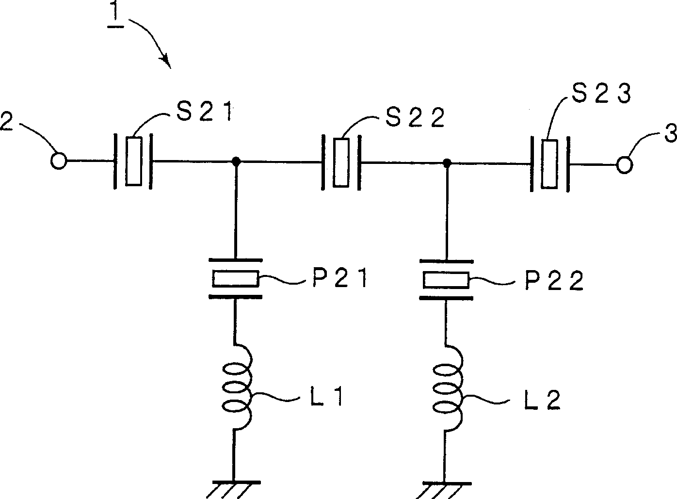
[0101] figure 1 is a circuit diagram of a ladder filter implemented as a filter device according to an embodiment of the present invention. The ladder filter 1 of this embodiment is a transmitter bandpass filter used in a W-CDMA multiplexer, its transmitting frequency band is 1920 MHz to 1980 MHz, and its receiving frequency band is 2110 MHz to 2170 MHz. Therefore the transmit band is lower than the receive band. That is, in a communication system including a first bandpass filter having a relatively lower passband and a second bandpass filter having a relatively higher passband, the ladder filter 1 is used as the first bandpass filter. A filter device for a pass filter.

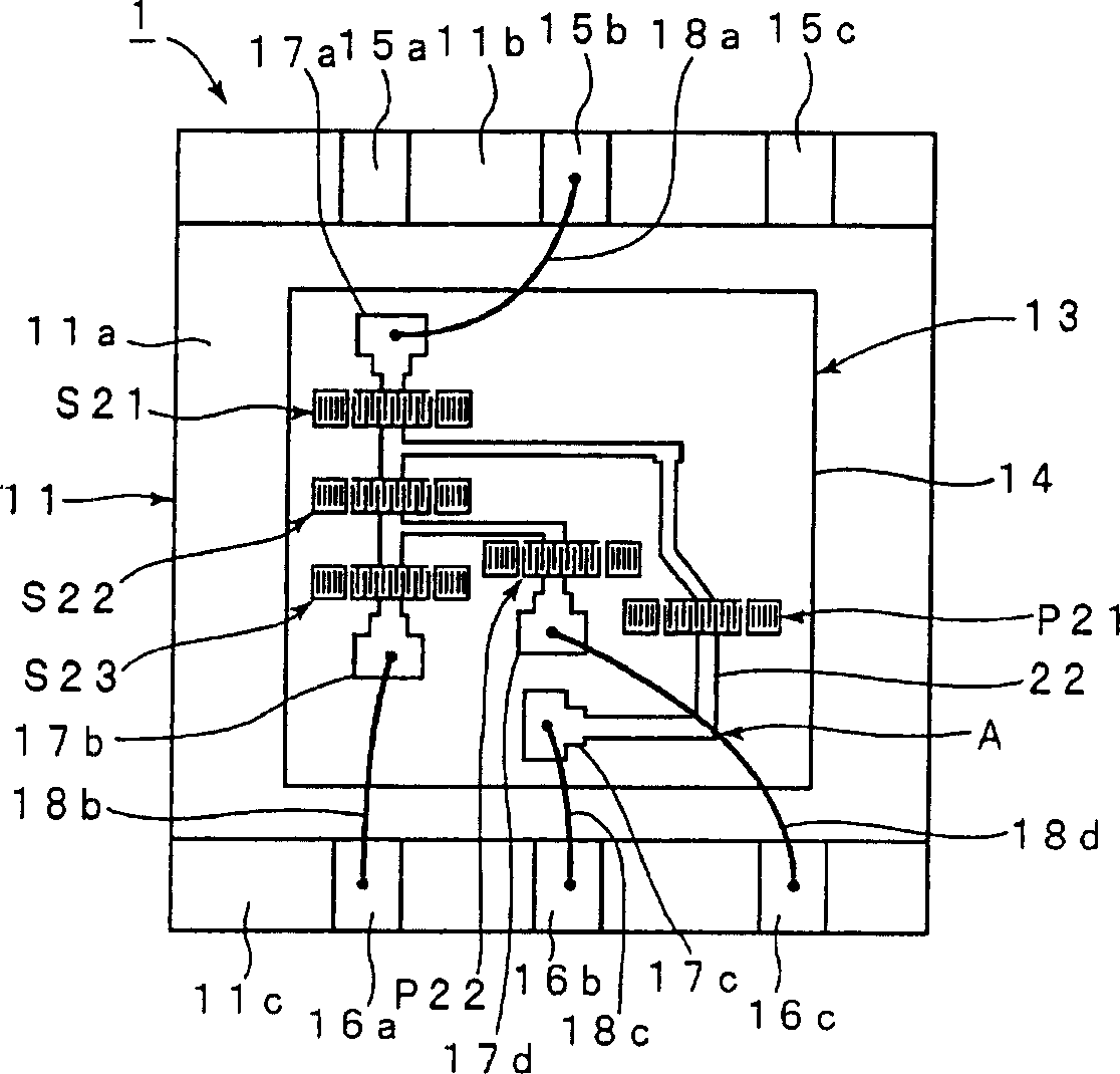
[0102] In the structure of the ladder filter 1, a plurality of surface acoustic wave resonators are connected to give a ladder circuit s...


PUM


Abstract

There is provided a low-loss and wide-band filter device capable of obtaining a sufficient attenuation amount. In a communication system including a first band pass filter having a relatively low pass band or a second band pass filter having a relatively high pass band, the filter device (1) is used as the first band pass filter. In the filter device (1), series arm oscillators (S21 to S23) are inserted into a series arm connecting an input terminal (2) and an output terminal (3). Parallel arm oscillators (P21, P22) are connected to a parallel arm connecting the series arm and the reference potential. At least one of the parallel oscillators (P21, P22) is connected in series to inductances (L1, L2). The resonance frequency of sub-resonance generated by insertion of the inductances (L1, L2) is positioned in the pass band, or in its vicinity, of the band filter of the reception side or the transmission side of the partner filter with respect to the ladder type filter.

Description

technical field [0001] The present invention relates to a filter arrangement having a plurality of resonators connected to provide a ladder circuit configuration, such as a transmitter bandpass filter and a receiver bandpass filter used in a communication system. Background technique [0002] In general, a ladder filter having a plurality of connected surface acoustic wave resonators is widely used as a receiver bandpass filter or a transmitter bandpass filter of a surface acoustic wave device. For example, Patent Document 1 discloses a ladder filter having a plurality of single-terminal pairs of surface acoustic wave resonators arranged alternately in a plurality of parallel branches and a series branch from the input side to the output side. on the road. In Patent Document 1, as Figure 24 As shown, a parallel branch resonator P1 is inserted in the parallel branch, while a series branch resonator S1 is inserted in the series branch. Although Figure 24 shows a one-stage ...

Claims


Application Information

Patent Timeline
Patent Type & Authority Applications(China)
IPC IPC(8): H03H9/58H03H9/17H03H9/64H03H9/70H03H9/72H03H9/05H03H9/60
CPCH03H9/605H03H9/6483H03H9/0557H03H9/1085H03H9/1071
Inventor 藤田茂幸谷口典生
Owner MURATA MFG CO LTD
Why Eureka
Try Eureka