
Optical image measuring apparatus

An optical image and detection device technology, which is applied to measurement devices, optical devices, diagnostic recording/measurement, etc., can solve the problems of limited freedom in device design, difficulty in image formation, and difficulty in efficiency.

Inactive Publication Date: 2006-04-26
KK TOPCON
View PDF9 Cites 2 Cited by
  • Summary
  • Abstract
  • Description
  • Claims
  • Application Information

AI Technical Summary

Problems solved by technology

Therefore, it is difficult to realize efficient image formation as shown in Patent Document 1 proposed by the present inventors.
[0023] On the other hand, in the optical image measuring device of Patent Document 3, the focused signal light is scanned to form an image of the object to be measured in the same manner, so it is difficult to improve the efficiency of measurement.
Moreover, the device can only be used with a Fizeau-type interferometer, so the degree of freedom in device design is limited

Method used


Image

  • Optical image measuring apparatus
  • Optical image measuring apparatus
  • Optical image measuring apparatus

Examples


Embodiment Construction

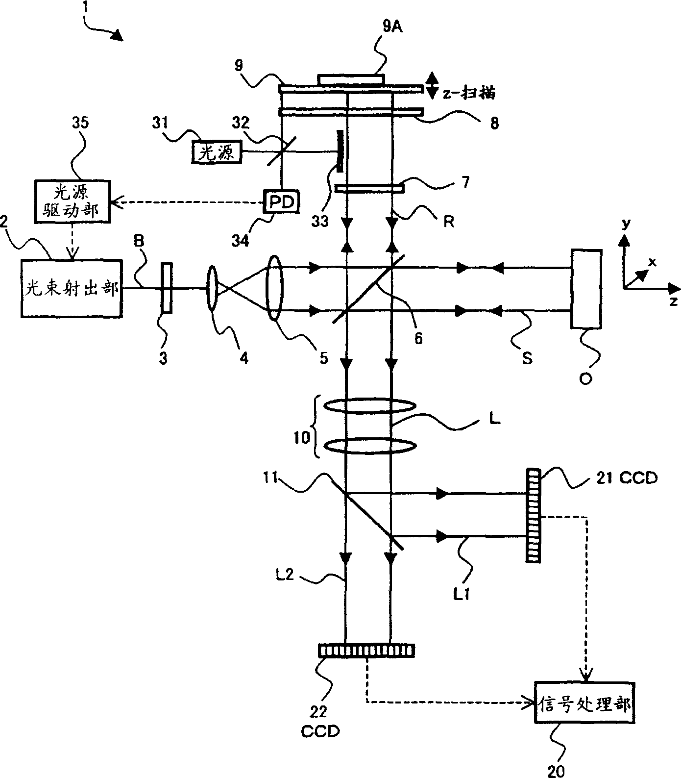
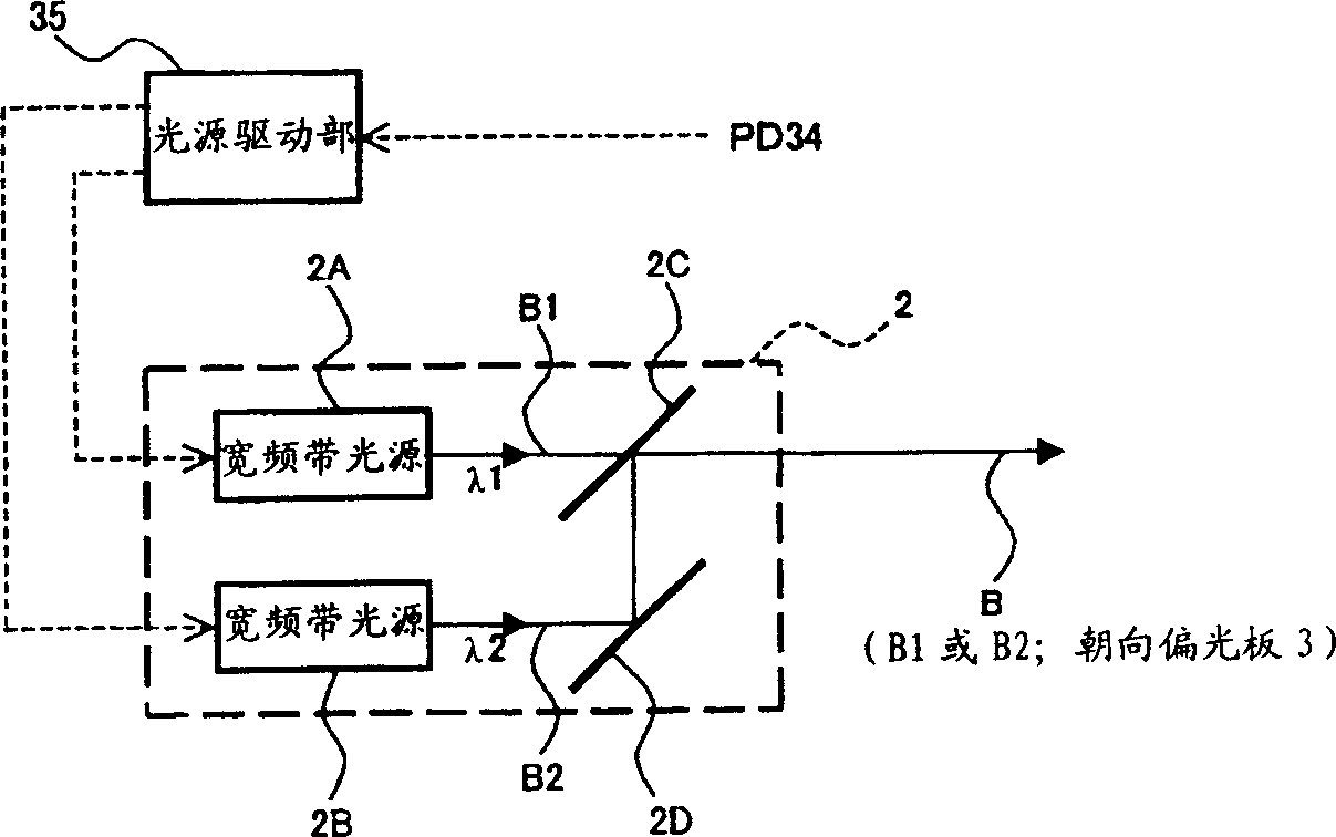
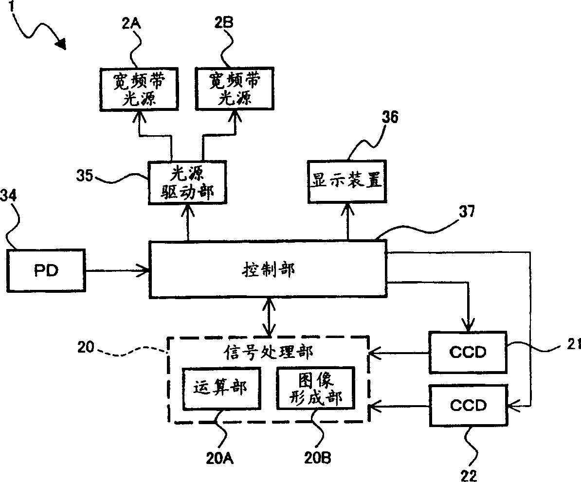
[0073] Preferred embodiments of the optical image measuring device of the present invention will be described in detail with reference to the drawings. Next, a first embodiment in which image measurement is performed using the polarization characteristic of light and a second embodiment in which image measurement is performed by sampling using a shutter will be described respectively. The optical image measurement device is used, for example, in the medical field to measure tomographic images and surface images of biological tissues and the like (objects to be measured).

[0074] (first embodiment)

[0075] (device configuration)

[0076] First of all, for the configuration of the optical image measuring device according to the first embodiment of the present invention, please refer to Figure 1 ~ Figure 4 It demonstrates in detail. figure 1 Shown is an example of the configuration of the (main body) optical system of the optical image measuring device according to this em...


PUM


Abstract

The present invention provides an optical image measurement device capable of efficiently forming an image for displaying functional information of biological tissue. Including: the beam emitting part 2 that periodically modulates the intensity of the beams B1 and B2 with different wavelengths and outputs them alternately, the polarizer 3 that converts the beam B into linearly polarized light, and divides the beam B into signal light S and reference light R half mirror 6, a wavelength plate 7 that converts the polarization characteristics of the reference light R, a frequency shifter 8 that shifts the frequency of the reference light R, and a half lens that superimposes the signal light S and the reference light R to generate interference light L Lens 6, polarizing beam splitter 11 for extracting a plurality of polarization components of interference light L, CCDs 21 and 22 for detecting each polarization component of extracted interference light L, and CCDs 21 and 22 for detecting light beams B1 and B2 respectively The signal processing unit 20 forms an image of the object O to be measured by interfering each polarization component of the light L.

Description

technical field [0001] The present invention relates to an optical image measuring device that irradiates a light beam to an object to be measured, which is a light scattering medium, and uses the reflected light or transmitted light to measure the surface shape and internal shape of the object to be measured and form an image thereof. , particularly relates to an optical image measurement device for measuring the surface morphology and internal morphology of an object to be measured by using an optical heterodyne detection method and forming an image. Background technique [0002] In recent years, attention has been drawn to optical image measurement technology that forms images of the surface and interior of an object to be measured using a laser light source or the like. Since this optical image measurement technology is not harmful to the human body like conventional X-ray CT (computer tomography, tomography), its application in the medical field is particularly expected...

Claims


Application Information

Patent Timeline
Patent Type & Authority Applications(China)
IPC IPC(8): G01N21/17G01N21/84
CPCA61B5/0066A61B5/14546A61B5/14551G01B9/02002G01B9/02007G01B9/02012G01B9/02069G01B9/02081G01B9/02091G01B2290/45G01B2290/70G01N21/21G01N21/3151G01N21/3563G01N21/359G01N21/4795G01N2021/1772G01N2021/1787G01N2201/0691
Inventor 陈建培秋叶正博
Owner KK TOPCON
Learn More