Fuel cell system operating at low temperature

A fuel cell system and fuel cell stack technology, which is applied in the fields of fuel cells, fuel cell additives, fuel cell heat exchange, etc., can solve the problems of less research on fuel cell systems.

Inactive Publication Date: 2006-07-19
田丙伦
View PDF0 Cites 2 Cited by
  • Summary
  • Abstract
  • Description
  • Claims
  • Application Information

AI Technical Summary

Problems solved by technology

However, combined with the operating environment such as ships, there are relatively few researches on fuel cell systems for water vehicles.

Method used


Image

  • Fuel cell system operating at low temperature

Examples


Embodiment Construction

[0021] The present invention will be further described below in conjunction with accompanying drawing.

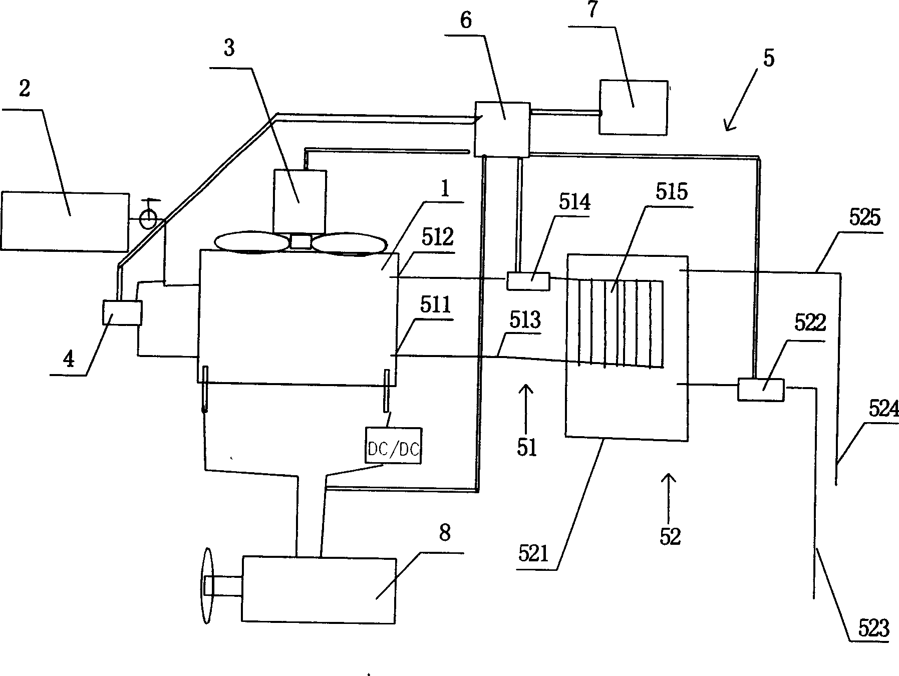
[0022] Such as figure 1 As shown, a low-temperature operating fuel cell system includes a fuel cell stack 1, a hydrogen tank 2, an oxygen supply fan 3, a hydrogen circulation pump 4, a water cooling cycle device 5, a control circuit 6, and a storage battery 7. The water cooling cycle The device 5 includes a circulating water cooling system 51 and a non-circulating water cooling system 52 .

[0023] The circulating water cooling system 51 includes a water cooling channel (not shown in the figure) in the fuel cell stack, a water cooling inlet 511 and an outlet 512 on the battery stack, a water cooling external circulation pipeline 513, a circulating water pump 514 and a cooling fin 515 composed of closed-circuit parts. The heat generated by the operation of the fuel cell is mainly taken away by the circulating water of the circulating water cooling system.

[0024] The non...


PUM


Abstract

The invention relates to a low-temperature fuel battery, which comprises a fuel battery pile, a hydrogen-feeding device, an oxygen-feeding device, a hydrogen cycle device, a water-cooling cycle device, and a control device. Wherein, said water cooling cycle device comprises a cycle water-cooling system and a non-cycle water cooling system. Compared to present technique, the invention has lower operation temperature without humidifying gas; simple system and stable operation, especial the prolonged service life of battery pile. The invention can apply the power source of ship and combine the operation condition to integrate the outer condition with said fuel battery system.

Description

technical field [0001] The invention relates to a fuel cell, in particular to a fuel cell system operating at low temperature. Background technique [0002] PEMFC fuel cell is a kind of H 2 and O 2 The device that converts the chemical energy generated by the reaction into electrical energy has the characteristics of starting at room temperature, high conversion efficiency, high specific power density, and zero pollution of the product. Fuel cells are widely used, and large fuel cells can be used as power sources for submarines, ships, and automobiles. Vehicle-mounted large-scale fuel cells have become a hot topic in the development of fuel cells. The world's major automobile companies are stepping up research and development of zero-emission green energy vehicles, which is driven by three aspects: environmental protection, oil shortage and emission policies. In order to solve the shortage of oil resources, adapt to the increasingly stringent exhaust emission standards, r...

Claims


Application Information

Patent Timeline
Patent Type & Authority Applications(China)
IPC IPC(8): H01M8/04H01M8/00H01M8/0267H01M8/04007H01M8/04029
CPCY02E60/50
Inventor 田丙伦
Owner 田丙伦
Why Eureka
Try Eureka