Ultrasonic electronic fuel carburetor

A technology of ultrasonic electronics and vaporization devices, which is applied in the direction of charging systems, combustion engines, internal combustion piston engines, etc., can solve the problems of large and uneven oil mist particles, and achieve the effects of complete combustion, sufficient vaporization, and sufficient oil and gas mixing

Inactive Publication Date: 2006-09-06
李伯清
View PDF0 Cites 1 Cited by
  • Summary
  • Abstract
  • Description
  • Claims
  • Application Information

AI Technical Summary

Problems solved by technology

However, from the perspective of "vaporization", it does not break away from the "negative pressure vaporization" principle of the "carburetor". It still mainly uses pressure to make fuel oil produce pressure difference atomization and splash atomization. Still large and uneven, still needs to be improved, which has important implications for today's energy shortage

Method used


Image

  • Ultrasonic electronic fuel carburetor
  • Ultrasonic electronic fuel carburetor
  • Ultrasonic electronic fuel carburetor

Examples


specific Embodiment approach

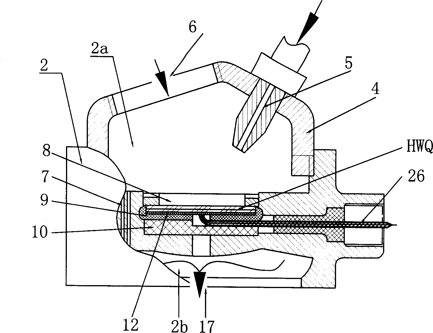
[0029] figure 1 It is shown that a specific embodiment of the present invention is: an automotive ultrasonic electronic fuel vaporization device, which is composed of an ultrasonic power source and a vaporization chamber 2, wherein the specific composition of the vaporization chamber 2 is: the inner cavity of the housing 4 The upper part of the vaporization chamber 2a and the lower part of the gas outlet chamber 2b are separated by a partition; the upper part of the vaporization chamber 2a is provided with an oil and gas inlet connected to the car carburetor, or the upper part of the vaporization chamber is provided with a fuel injection connected to the car fuel pump Port 5 and the air inlet 6 connected to the automobile air filter; the ultrasonic transducer HWQ is fixed in the middle of the partition, and the air gap 7 connecting the vaporization cavity 2a and the outlet cavity 2b is provided on the partition; the lower part of the outlet cavity 2b A mixed gas outlet 17 connec...

Embodiment 2

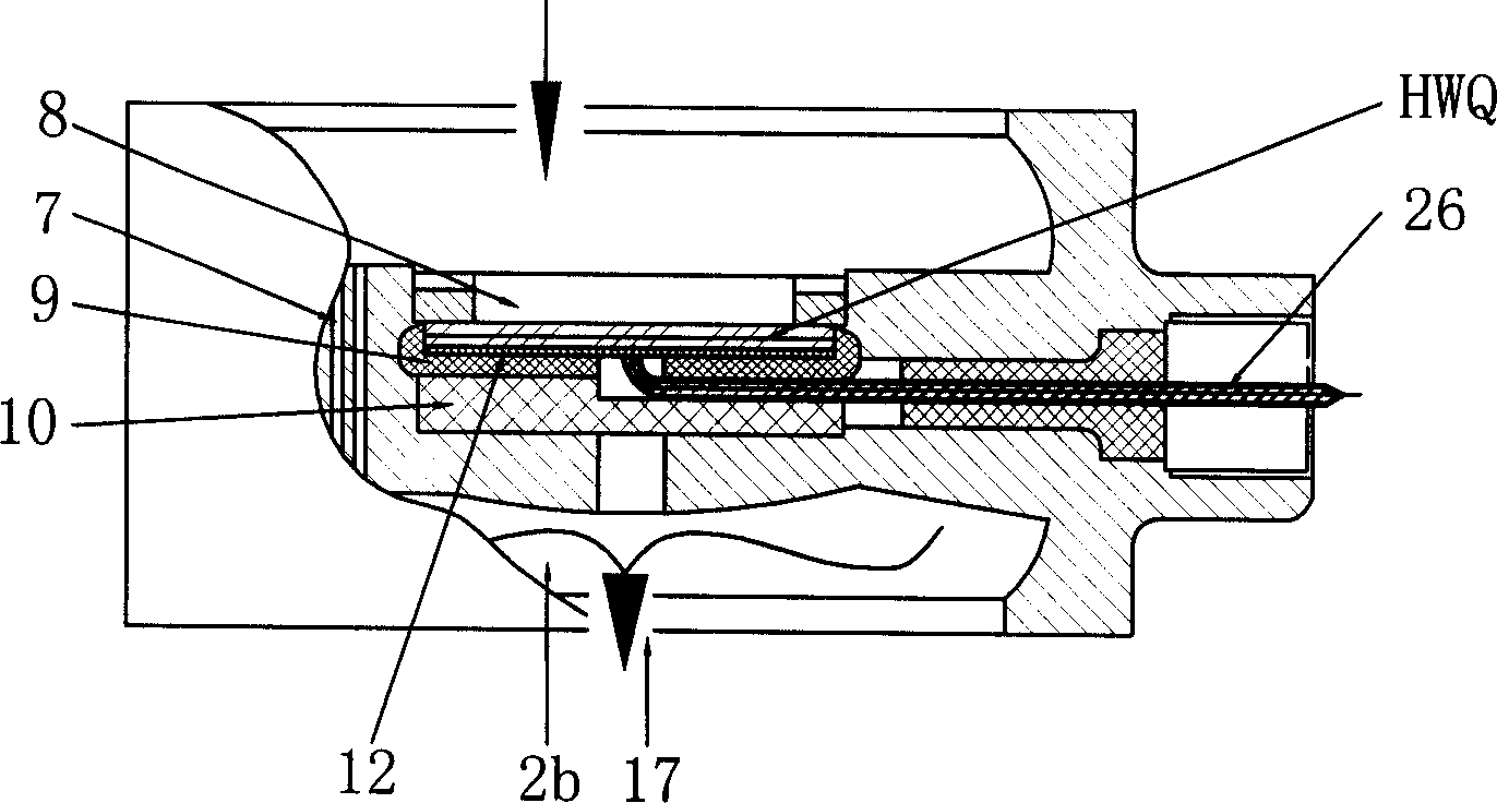
[0037] figure 2 It is shown that this embodiment is basically the same as the first embodiment, except that the upper part of the vaporization chamber does not have the fuel injection port 5 and the air intake port 6, but an oil and gas inlet connected to the car carburetor.

[0038] The device of the present invention can be installed on a single combustion chamber of an engine to realize single-chamber vaporization, and multiple combustion chambers can be installed at the same time to realize multi-chamber vaporization to ensure complete vaporization.

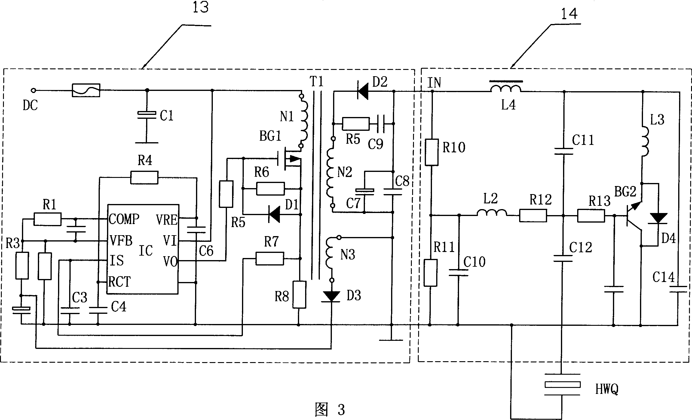
[0039] When the present invention is actually implemented, the switching regulated power supply can be replaced with other circuits that can transform the 12V direct current of the automobile engine into a matching ultrasonic power source input voltage. The ultrasonic power source can also use other circuits that can generate ultrasonic frequencies and whose power is adapted to the ultrasonic transducer.


PUM


Abstract

The invention discloses a vehicle ultrasonic electric fuel gasify device, which is formed by an ultrasonic power resource and a gasify room. Wherein, the gasify room comprises a frame whose inner chamber is separated by baffle plate into the upper gasify chamber and the lower outlet chamber; the upper part of gasify chamber has a oil inlet connecting the vehicle carburetor or has a oil injection hole connecting the fuel pump and the inlet connecting the air filter; the middle part of baffle plate is fixed with a ultrasonic energy exchanger; the baffle pate has air seams connecting the gasify chamber and the gas chamber; the lower part of outlet chamber has a mixed gas outlet connecting the mixed gas distribution pipeline; the down-lead of ultrasonic energy exchanger through the lead hole of frame is connected to the ultrasonic power resource. The invention can reduce the size of particle generating by gasifying the fuel, to make the fuel burn safer and improve the heat efficiency and discharge standard of fuel engine.

Description

[0001] Field [0002] The invention relates to an automobile ultrasonic electronic fuel vaporization device. Background technique [0003] "Fuel vaporization" is a key research topic in the field of fuel engine technology. It is the main factor that affects the thermal efficiency and emission indicators of the engine, and is of great significance to energy conservation and environmental protection. Therefore, the fuel vaporization device is an important part of the fuel engine. The fuel vaporization device used to use a "carburetor", which uses the negative pressure generated in the combustion chamber of the engine's intake stroke to form differential pressure atomization and splash atomization of the fuel, and at the same time uses the engine's thermal energy to form evaporative atomization. After its treatment, the oil mist particles are large and uneven, and consume a lot of fuel, which has been eliminated. At present, most of the fuel vaporization devices are electronic fuel in...

Claims


Application Information

Patent Timeline
Patent Type & Authority Applications(China)
IPC IPC(8): F02M27/08
CPCY02T10/126Y02T10/12
Inventor 李伯清
Owner 李伯清
Why Eureka
Try Eureka