Three level inverter control system and method

A technology of three-level inverter and control method, which is applied in the direction of converting irreversible DC power input into AC power output, etc., which can solve the problem that the control signal cannot be changed quickly, the digital implementation has a large amount of calculation, and the system has poor rapidity, etc. problem, to achieve the effect of overcoming the difficulty of low output voltage control, good real-time performance, and simple control method

Inactive Publication Date: 2006-09-06
GUANGDONG MINGYANG LONGYUAN POWER ELECTRONICS
View PDF0 Cites 41 Cited by
  • Summary
  • Abstract
  • Description
  • Claims
  • Application Information

AI Technical Summary

Problems solved by technology

[0005] The advantage of the three-level space vector control SVPWM method is mainly that the voltage utilization rate is high. For the conversion circuit of the diode mid-point clamp, the voltage vector (generally a small vector) can be used to achieve the balance of the DC side capacitor voltage; the disadvantage is that the digital It is very computationally intensive to implement
For another example, the original three-level PWM control system of Mingyang Company in Zhongshan City adopts specific harmonic elimination pulse width modulation control (referred to as harmonic elimination method), which calculates the switching time corresponding to each frequency in advance and stores it in the memory. , to generate a control signal, the control signal cannot be changed quickly, so the rapidity of the system is not good, and it takes up a lot of memory

Method used


Image

  • Three level inverter control system and method
  • Three level inverter control system and method
  • Three level inverter control system and method

Examples


Embodiment Construction

[0037] Below in conjunction with accompanying drawing and specific embodiment the present invention is described in further detail:

[0038] (I. Overview

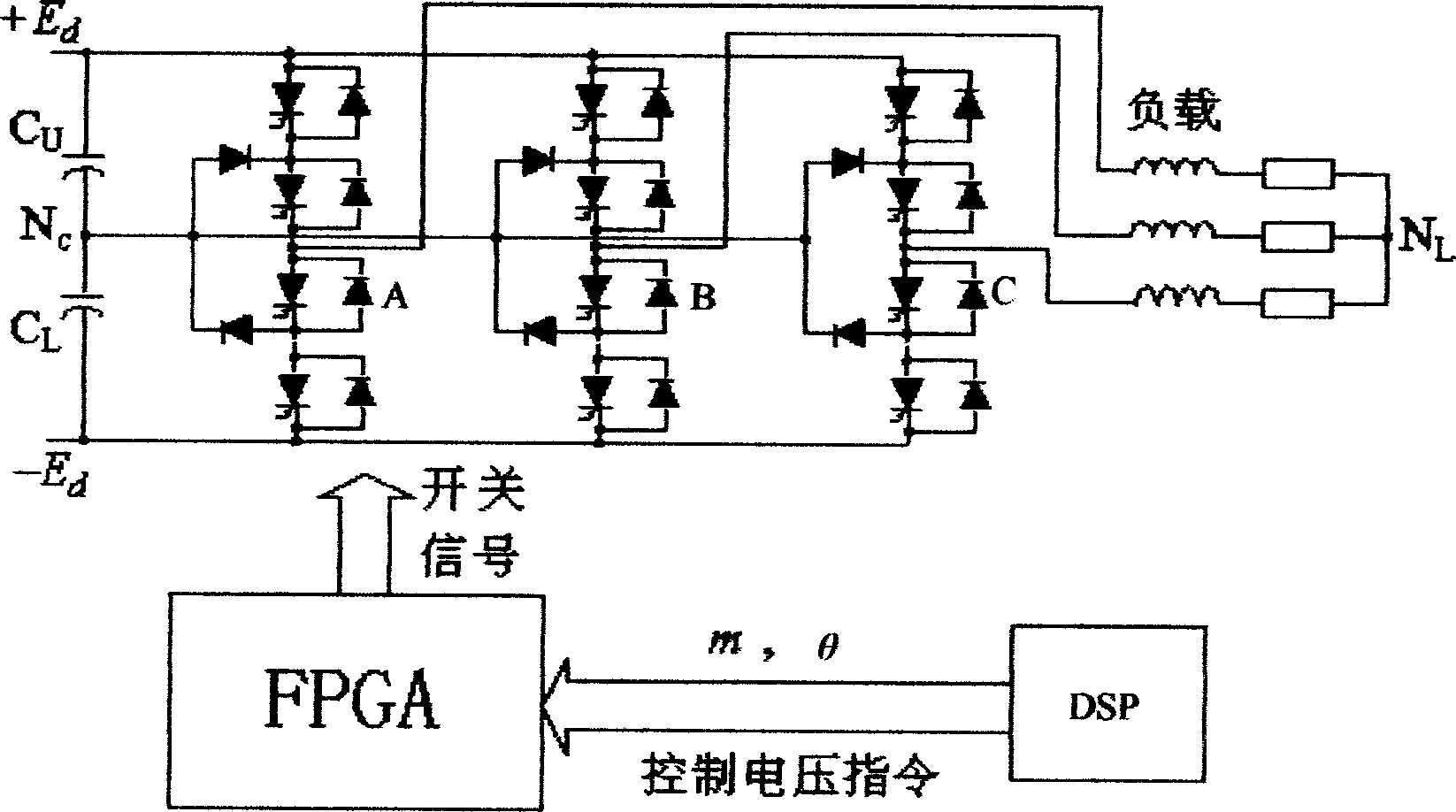
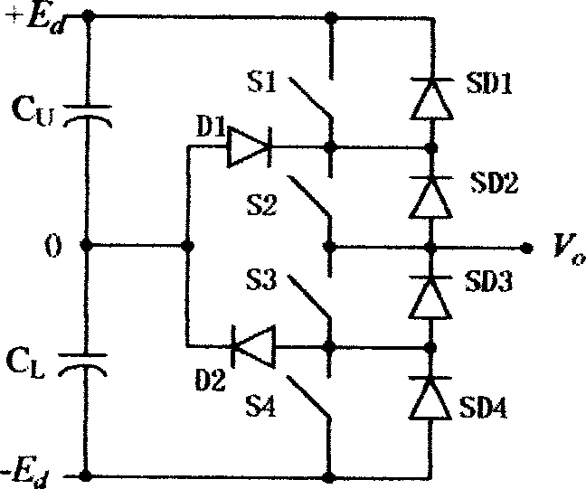
[0039] The main circuit of the three-level inverter is shown in figure 1 . Each phase bridge arm is composed of 4 switching devices and 2 clamping diodes, and the output has three working states: "+"—+E d ; "0"—0V; "-"——E d . Thus, a three-valued switch function can be defined, such as S A (1, 0, -1) means the three voltage states of the AC side voltage of phase A, and the conditions of each phase are the same, so it is deduced that the three-phase output of the three-level inverter has a total of 3 3 = 27 states, defined according to the voltage space vector

[0040]

[0041] where S A , S B and S C is the switching function of A, B, C three-phase output state, S m =1 represents the "+" state, 0 represents the "0" state, and -1 represents the "-" state. These 27 states constitute a total of 19 voltage vectors...


PUM


Abstract

The present invention discloses a three electric level inverter control system. It contains three electric level voltage source inverter (NPC), field programmable gate array (FPGA), digital signal processor (DSP), wherein FPGA field programmable gate array (FPGA) receiving digital signal processor (DSP) sent control voltage instruction generating three electric level voltage source inverter (NPC) control signal. The present invention also discloses three level inverter control method, featuring 1, digital signal processor (DSP) transmitting space voltage vector amplitude value m and argument for controlling three level inverter triphase reference voltage, 2, field programmable gate array (FPGA) receiving DSP sent space voltage vector amplitude value m and argument, generating signal Vca, Vcb, Vcc, through direct current biasing and dead zone compensation techniques processing to generate three-phase voltage modulation signal Vca **, Vcb **, Vcc **, 3, finally respectively comparing with positive triangular wave, negative triangular wave to generate control pulse. The present invention overcomes the insufficiency of current pulse width modulation method (SVPWM) and special harmonic cancellation method (SHE-PWM), provides a fine rapidity, simple controlling, and practical three level inverter control system and method.

Description

【Technical field】 [0001] The invention relates to a three-level inverter control system and method, in particular to a three-level inverter control system and method based on sine wave modulation and using DC bias technology and dead zone compensation technology. The utility model belongs to the field of frequency conversion speed regulating devices for large-capacity, medium-high voltage asynchronous motors. 【Background technique】 [0002] Three-level inverters have been widely used in high-power frequency conversion speed regulation, power system active filtering and dynamic reactive power compensation and other fields. With the improvement of voltage and current levels of high-voltage IGBT (insulated gate bipolar transistor), IGCT (integrated gate commutated thyristor), IEGT and other devices, this topology will be more widely used. Midpoint clamping three-level conversion is one of the most commonly used topologies in the field of high power and medium voltage (1-6KV), ...

Claims


Application Information

Patent Timeline
Patent Type & Authority Applications(China)
IPC IPC(8): H02M7/48
Inventor 严长辉魏学森金曙光
Owner GUANGDONG MINGYANG LONGYUAN POWER ELECTRONICS
Why Eureka
Try Eureka