Dynamic ice-storage energy saving unit

An energy-saving unit and ice storage technology, which is applied in heating methods, lighting and heating equipment, applications, etc., can solve the problems of unintuitive ice storage status, complex structure, and increased floor space, so as to achieve intuitive ice storage status and system operation. Reliable, footprint-saving effect

Inactive Publication Date: 2006-10-04
广东惠生能源技术有限公司
View PDF0 Cites 17 Cited by
  • Summary
  • Abstract
  • Description
  • Claims
  • Application Information

AI Technical Summary

Problems solved by technology

The existing ice-storage air-conditioning system is based on the traditional refrigeration unit with an additional ice-storage tank, which not only increases the floor area, but also increases the equipment investment cost; most of the existing ice-storage systems use 25% to 30% % ethylene glycol aqueous solution is used as the refrigerant, and the ethylene glycol aqueous solution pipeline needs to be installed. Its structure is complex, the system operation is unreliable, and maintenance is troublesome. In addition, the ice storage process is carried out in the ice storage tank, and the ice storage state is not intuitive. Ice making efficiency is low, ice melting is slow and cooling temperature is unstable
[0004] Therefore, the existing technology has the following disadvantages: large floor area, complex structure, troublesome maintenance, high investment and operating costs, unintuitive ice storage status, low ice production efficiency, slow ice melting and unstable cooling temperature

Method used


Image

  • Dynamic ice-storage energy saving unit

Examples


Embodiment Construction

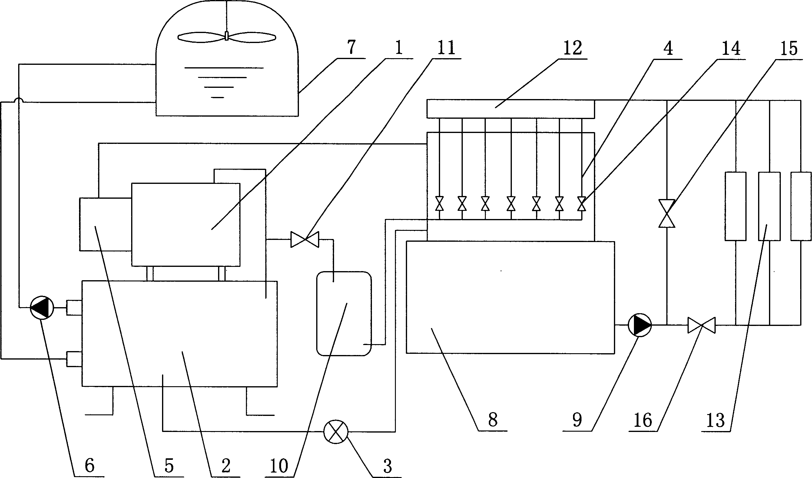
[0011] Such as figure 1 As shown, the present invention includes a chiller, a refrigerating fluid cooling water circulation system, an ice storage system, an indoor cooling system, a computer automatic control device, an air tank 10, and a water distributor 12. The chiller includes a compressor 1, a condenser 2. The throttle valve 3, the evaporator 4, and the accumulator 5 are connected in turn through the refrigerant pipeline to form a circulation loop. The refrigerant cooling water circulation system includes a condenser 2, a cooling water pump 6, and a cooling tower 7. The ice storage system includes an evaporator 4, an ice storage tank 8, a circulating water pump 9, and an I solenoid valve 15 sequentially connected by a cooling water circulating water pipe to form a circulation loop. The indoor cooling system includes an ice storage tank 8, a circulating water pump 9, an II solenoid valve 16, and an indoor heat exchanger 13, which are connected in turn through a cooling water ...


PUM


Abstract

The invention discloses a dynamic ice-reserving energy-saving set in the air-conditioner power-saving domain, which comprises the following parts: compressor (1), condenser (2), choke valve (3), evaporator (4), reservoir (5), cooling pump (6), cooling tower (7), ice-reserving groove (8), circulating pump (9), indoor heat exchanger (13), gas-reserving cylinder (10) and water-locator (12), wherein the evaporator (4) is board-typed exchanger, which lies on the ice-reserving groove (8); the inlet of gas-reserving cylinder (10) connects the refrigerating working pipe between compressor (1) and condenser (2), whose outlet parallels several IV electromagnetic valves (14) in the inlet of board-typed exchanger working side.

Description

Technical field [0001] The invention relates to a dynamic ice storage energy-saving unit. Background technique [0002] Air-conditioning energy storage technology is a practical comprehensive technology that has emerged in China since the 1990s. It can shift the peak and fill valleys of the power grid, and is beneficial to the optimal allocation of social resources. At the same time, due to the peak and valley price of electricity The difference is that the air-conditioning energy storage technology has greatly reduced the user's operating electricity bill, so it is a technology that benefits the country and the people. Energy storage air conditioners use energy storage devices to store energy during a time when the air conditioning system does not require energy or uses a small amount of energy, and releases this part of energy when the air conditioning system requires a large amount of energy. According to the object of use and storage temperature, it...

Claims


Application Information

Patent Timeline
Patent Type & Authority Applications(China)
IPC IPC(8): F24F5/00F25D3/04
Inventor 聂民杨文
Owner 广东惠生能源技术有限公司
Why Eureka
Try Eureka