Method for manufacturing high precision antenna reflection surface without honeycomb interlayer

A technology of honeycomb interlayer and reflective surface, which is applied to antennas, electrical components, etc., can solve the problems of not being suitable for large-scale antennas and mass production, high weight and cost of reflective surface products, and complicated manufacturing process, so as to achieve excellent molding accuracy and improve The effect of performance-price ratio and simplification of the manufacturing process

Inactive Publication Date: 2006-10-11
NO 54 INST OF CHINA ELECTRONICS SCI & TECH GRP
View PDF1 Cites 17 Cited by
  • Summary
  • Abstract
  • Description
  • Claims
  • Application Information

AI Technical Summary

Problems solved by technology

[0003] Although the traditional machining method can produce ideal precision with metal reflector blanks, its shortcomings are limited to the manufacture of single-piece and small antenna reflectors, and due to the machining process requirements, the final processed Reflector products have a large weight and high cost, which constitutes a key technical weakness in the manufacture of antenna reflectors in high-precision applications, especially not suitable for large-scale antennas and mass production requirements
[0004] Chinese patent application No. 200510012407.7, titled "A Method for Manufacturing a High-Precision Antenna Reflecting Surface", discloses a method for manufacturing a high-precision antenna reflecting surface with a honeycomb interlayer. The buffering effect of the honeycomb interlayer between the curved panels greatly improves the manufacturing accuracy of the antenna reflector, but there are disadvantages of complex manufacturing process and high cost

Method used


Image

  • Method for manufacturing high precision antenna reflection surface without honeycomb interlayer
  • Method for manufacturing high precision antenna reflection surface without honeycomb interlayer
  • Method for manufacturing high precision antenna reflection surface without honeycomb interlayer

Examples


Embodiment Construction

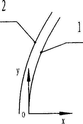
[0025] The best embodiment of the present invention is shown in Figure 1 and includes the following steps:

[0026] (1) In the XOY coordinate system, design the theoretical skin curve of the working reflective surface, and use the theoretical skin curve as the generatrix to rotate around the x-axis to form a theoretical skin surface 1, such as Picture 1-1 .

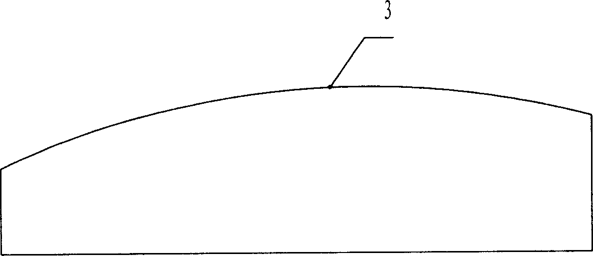
[0027] (2) According to the theoretical skin surface 1 design the skin surface drawing mold table 3 of the reflective surface unit. The reflective surface of large and medium-sized antennas is generally divided into a variety of smaller reflective surface units to adjust and assemble, and the same reflective surface unit adopts the same Manufacture of a drawing die set. The skin surface drawing mold table 3 adopts a cast iron material, and its surface is processed by a numerical control machine to form a high-precision skin surface, such as Figure 1-2 .

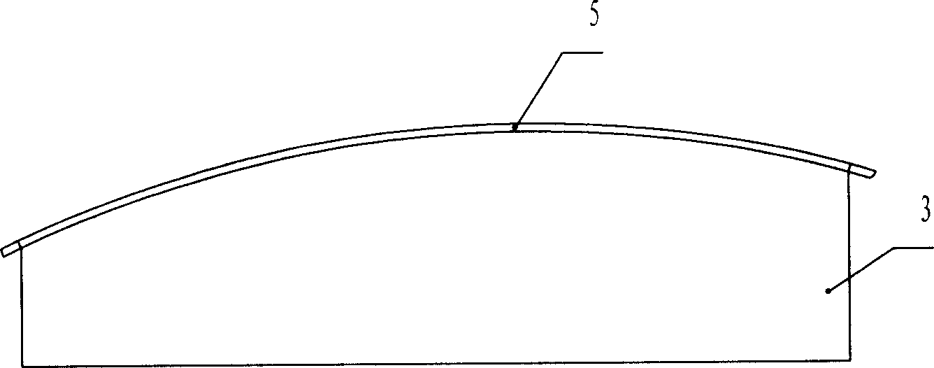
[0028] (3) Using anti-rust aluminum sheet or aluminum alloy sheet aft...


PUM

PropertyMeasurementUnit
Thicknessaaaaaaaaaa
Thicknessaaaaaaaaaa

Abstract

The disclosed manufacture method for a high-precision antenna reflecting plane without honeycomb sandwich comprises: with skin-surface stretching module desk as base, adhesive as medium and skin-surface plate as the operating plane for reflecting plane unit, sticking directly the plate on supporting backbone surface with vacuum negative-pressure technique to obtain the final product. With simple structure and reliable property, this invention benefits to batch production.

Description

Technical field [0001] The invention relates to a method for manufacturing a high-precision antenna reflection surface without a honeycomb sandwich in the field of communication and measurement and control, and is particularly suitable for working in high frequency bands, especially Ka frequency bands of various calibers and various forms of reflection surface antennas used as high-precision antennas. , Large rigidity, light weight and mass production of outdoor working antenna reflective surface. Background technique [0002] With the rapid development of communication and measurement and control technology, the working frequency band is getting higher and higher, so the requirements for the high precision of the antenna reflection surface are getting higher and higher. The reflection surface of the reflection surface antenna currently working in the high frequency band, especially working in the Ka frequency band There are only traditional machining methods and flexible mold pr...

Claims


Application Information

Patent Timeline
IPC IPC(8): H01Q15/14
Inventor 冯贞国白玉魁武玉庭周书中张文静
Owner NO 54 INST OF CHINA ELECTRONICS SCI & TECH GRP
Why Eureka
Try Eureka