

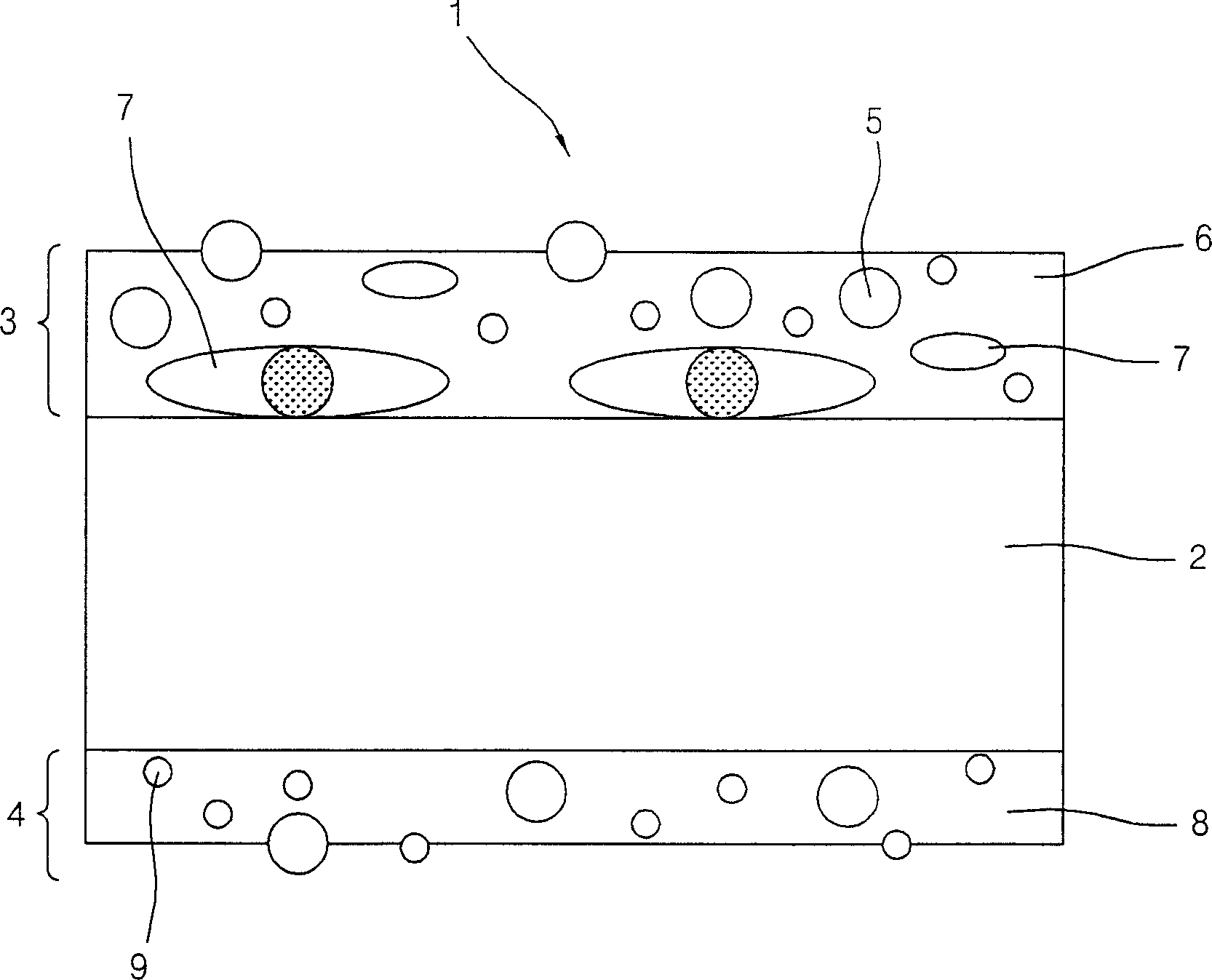
Light-diffusing film having pores
A technology of air holes and light film, which is applied in the field of astigmatism film, and can solve the problems of increasing the transmittance and diffusivity of the astigmatism film
- Summary
- Abstract
- Description
- Claims
- Application Information
AI Technical Summary
Problems solved by technology
Method used
Image

Examples
Embodiment 1
[0030] On one surface of a highly transparent polyester film (XG533-100 μm, from Toray Saehan Inc.) the astigmatism layer uses the chemical composition ratio of Table 1, applies a diecoater (diecoater) under the processing conditions of Table 1, and dries for 60 seconds at 110 ° C. A light-scattering layer having a size of 30 μm was formed.
[0031] total weight of ingredients
100g
Astigmatism layer composition
Astigmatism resin
Acrylic resin (A-811, Aekyung Chemical Co., Ltd.
(Aekyung Chemical Co. Ltd.)
30g
astigmatism particles
SOKEN MX1000 (diameter: 10μm)
30g
(Methylethylketone)
40g
synthetic pressure
3kgf / cm 2
Substrate moving speed
40m / min
[0032] The composition ratio of the anti-blocking layer coated on the other surface of the astigmatism film by Mayer bar is shown in Table 2 belo...
Embodiment 2
[0035] The light-scattering layer according to the ratio of synthetic components in the following table 3 was applied to one surface of a highly transparent polyester film (XG533-100 μm, from Toray Saehan Inc.), using a Mayer rod, and then dried at 110° C. for 60 seconds, A light-scattering film having a light-scattering layer with a thickness of 5 μm was formed.
[0036] total weight of ingredients
100g
Astigmatism layer composition
astigmatism resin
Acrylic resin (A-811, Aekyung Chemical Co., Ltd.
Chemical Co. Ltd.))
30g
Astigmatism particles
SOKEN MX1000 (diameter: 10μm)
30g
40g
Precision ball 50D, (0.1wt based on the total weight of the ingredients)
0.1g
The pressure exerted by the synthesis
3kgf / cm 2
Substrate moving speed
40m / min
[0037] The composition ratio of the anti-blocking layer...
experiment example
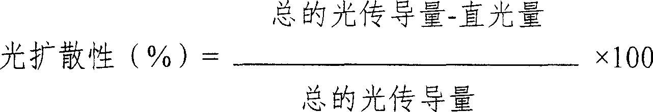
[0045] 1. Measurement of total light transmittance and light diffusivity
[0046] The light transmittance and light diffusivity of the light-scattering film in Examples 1-2 and Comparative Example 1 were measured according to the following procedure. When the 550nm light passes through the 10cm×10cm sized, upright astigmatism film sample perpendicularly, the amount of light is measured with an automatic digital hazemeter, which is selected from Nippon Denshoku Industries Co. , Ltd.), the calculation of light diffusivity (haze) adopts the following formula 1:
[0047] Formula 1
[0048]
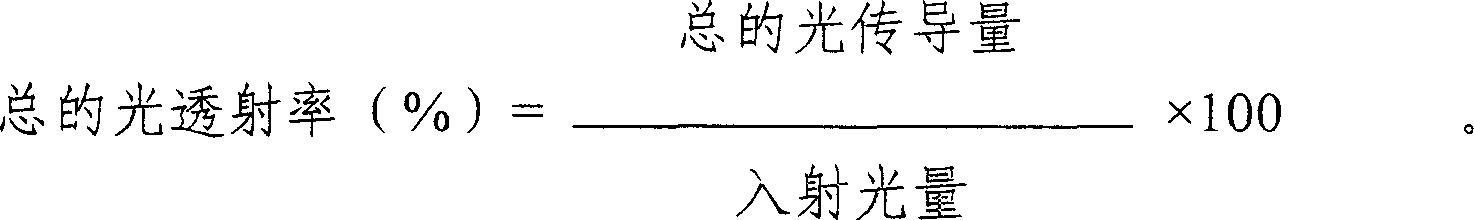
[0049] In addition, the calculation of the total light transmittance adopts the following formula 2:
[0050] Formula 2
[0051]
[0052] 2. Measurement of porosity
[0053] The porosity of each astigmatism mold produced in Examples 1 to 2 and Comparative Example 1, the measurement of Comparative Example 1 was processed by mercury penetration of micrometric method Micro Metrics using...
PUM
| Property | Measurement | Unit |
|---|---|---|
| thickness | aaaaa | aaaaa |
| thickness | aaaaa | aaaaa |
| thickness | aaaaa | aaaaa |
Abstract
Description
Claims
Application Information