Scan probe microscope, sample observation method using same and method for manufacturing the device

A scanning probe and microscope technology, applied in the field of scanning probe microscope technology, can solve problems such as probe wear, difficult to measure shape, difficult to measure shape, etc., to achieve the effect of measurement, high-precision measurement, and high-speed approach

Inactive Publication Date: 2006-11-01
HITACHI LTD
View PDF3 Cites 36 Cited by
  • Summary
  • Abstract
  • Description
  • Claims
  • Application Information

AI Technical Summary

Problems solved by technology

(3) Questions about measurement objects
[0010] In other words, in the technique disclosed in the above-mentioned patent document, for a sample with a large aspect ratio, the probe slightly slips at the steeply inclined portion, and the measured shape is deformed, making it difficult to measure the correct shape.
In addition, the probe is worn due to the sliding and vibration of the probe, making it difficult to measure the shape stably and with high precision.

Method used


Image

  • Scan probe microscope, sample observation method using same and method for manufacturing the device
  • Scan probe microscope, sample observation method using same and method for manufacturing the device
  • Scan probe microscope, sample observation method using same and method for manufacturing the device

Examples


Embodiment 1

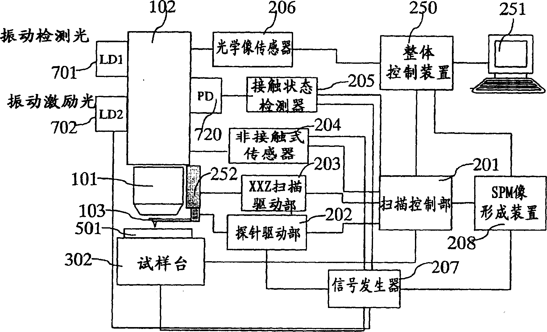
[0042] figure 1 A configuration diagram showing a scanning probe microscope according to Example 1 of the present invention. A sample 501 is placed on a sample stage 302 drivable in X, Y, and Z directions, and is controlled by a scanning control unit 201 . The probe moving mechanism 252 to which the probe 103 is attached is driven in the X, Y, and Z directions by signals from the XYZ scanning drive unit 203 , thereby performing probe scanning of the scanning probe microscope.

[0043] A signal from the probe drive unit 202 can generate minute vibrations in the probe 103 itself or in an actuator composed of a piezoelectric element or the like arranged at the base of the probe. Or, as another example, the signal from the probe driving unit 202 can also be superimposed on the signal from the XYZ scanning driving unit 203, and by causing micro-vibration in the probe moving mechanism, the mounted probe 103 Excited to vibrate. Alternatively, as will be described later, it is also...

Embodiment 2

[0077] Figure 6 It is a figure showing the optical system of the scanning probe microscope of Example 2 of this invention. The light emitted from the light source 111 is converted into parallel light by the lens 112 , reflected by the mirror 113 , enters the lens 101 , and then focuses on the sample 501 . Depending on the shape of the aperture incorporating the light source 111, an image of any shape such as a dot or a slit can be formed. The light reflected by the sample passes through the objective lens again, is reflected by the mirror 114 , and is imaged on the detector 116 by the imaging lens 115 . The position of the image moves according to the height of the sample 501 . Assuming that the incident angle of the detection light 110 on the sample is θ, the imaging magnification of the lens 115 is m, and the height of the sample is Z, the amount of movement is 2mZtanθ, so the height of the sample can be detected by measuring the amount of movement .

[0078] As long as...

Embodiment 3

[0086] Figure 7 An optical system according to Example 3 of the present invention is shown. In Embodiment 2, so-called heterodyne detection using dual-frequency light is utilized, but homodyne detection using single-frequency light may be used instead. At this time, the light of frequency f1 is branched and used as reference light 792, and then detected on the photodiode. This point does not change, but to detect the phase, as Figure 7 As shown, the laser beam is branched by the half mirror 726, and reflected by the mirror 727 on the other hand. After the phase difference between the reference light and the detection light is shifted by 90 degrees by the λ / 4 plate 728, interference is generated by the polarizer 721'. After passing through the lens 729', it is detected by the second photodiode 720'. The signals from the first and second photodiodes 720 and 720' are signals corresponding to cos and sin, and after detecting the amplitude of the component corresponding to the ...


PUM


Abstract

The present invention provides a scanning probe microscope, a sample observation method using the same, and a device manufacturing method that can measure accurate three-dimensional shape information of a sample without destroying the sample with a high total throughput, and can measure Correct three-dimensional shape information for walls or overhanging specimens. When the probe is brought into contact only at the measurement point, when moving to the next measurement point, once the probe is raised and retracted, the probe is moved to the next measurement point, and the probe is approached without damaging the sample. In the three-dimensional shape method, high-frequency, small-amplitude cantilever vibration and vibration detection are performed, and lateral vibration or vertical and horizontal vibration are performed to improve the contact force detection sensitivity at steep slopes. It has a part that tilts the probe according to the tilt of the measurement object and can absorb the large change in the direction of the light reflected by the cantilever for detecting the contact state of the probe and the sample with the tilt of the probe. or adjusted structure.

Description

technical field [0001] The present invention relates to a scanning probe microscope technique, a sample observation method using the same, and a device manufacturing method. Background technique [0002] A scanning probe microscope (SPM: Scanning Probe Microscope) is known as a technique for measuring a microscopic three-dimensional shape. This is a technique that scans a sample while controlling a pointed probe while keeping the contact force at a very small value, and is widely used as a technique that can measure microscopic three-dimensional shapes at the atomic level. [0003] On the other hand, currently, in the microscopic pattern formation process of LSI, dimension management using CD-SEM (length measuring SEM) is performed, but the following limit appears as the pattern becomes microscopic. (1) The problem of measurement accuracy. The gate pulse width of the 65nm node LSI that will become the mainstream in 2007 is 25nm. If the allowable error is 10% and the measur...

Claims


Application Information

Patent Timeline
Patent Type & Authority Applications(China)
IPC IPC(8): G02B21/00G01Q60/34
Inventor 渡边正浩中田俊彦马场修一
Owner HITACHI LTD
Why Eureka
Try Eureka