Removal method and equipment for sucking ammonia nitrogen in waste water through negative pressure of vacuum

A technology of vacuum negative pressure and vacuum suction, applied in the field of water treatment, can solve the problems of high corrosion resistance and high temperature and high pressure requirements, consumption of large chemicals or energy, impossible ammonia removal method, etc., achieving strong practicability and easy promotion. , the effect of low operating costs

Inactive Publication Date: 2006-12-06
WUHAN UNIV OF TECH
View PDF0 Cites 15 Cited by
  • Summary
  • Abstract
  • Description
  • Claims
  • Application Information

AI Technical Summary

Problems solved by technology

Although their denitrification efficiency can be very high (for example, when pH=10.8, temperature 255°C, and pressure 4.2MPa, 1023mg/L ammonia nitrogen wastewater is treated, NH 3 -N removal rate can reach 98%), however, in general, expensive noble metal catalysts are required, and there are high requirements for corrosion resistance and high temperature and pressure resistance for reactors and pump equipment, so it is not possible to become widely used for the time being Ammonia removal method
[0024] In summary, the existing de-NH 3 Among the industrial water treatment technologies for -N

Method used


Image

  • Removal method and equipment for sucking ammonia nitrogen in waste water through negative pressure of vacuum
  • Removal method and equipment for sucking ammonia nitrogen in waste water through negative pressure of vacuum
  • Removal method and equipment for sucking ammonia nitrogen in waste water through negative pressure of vacuum

Examples


Example Embodiment

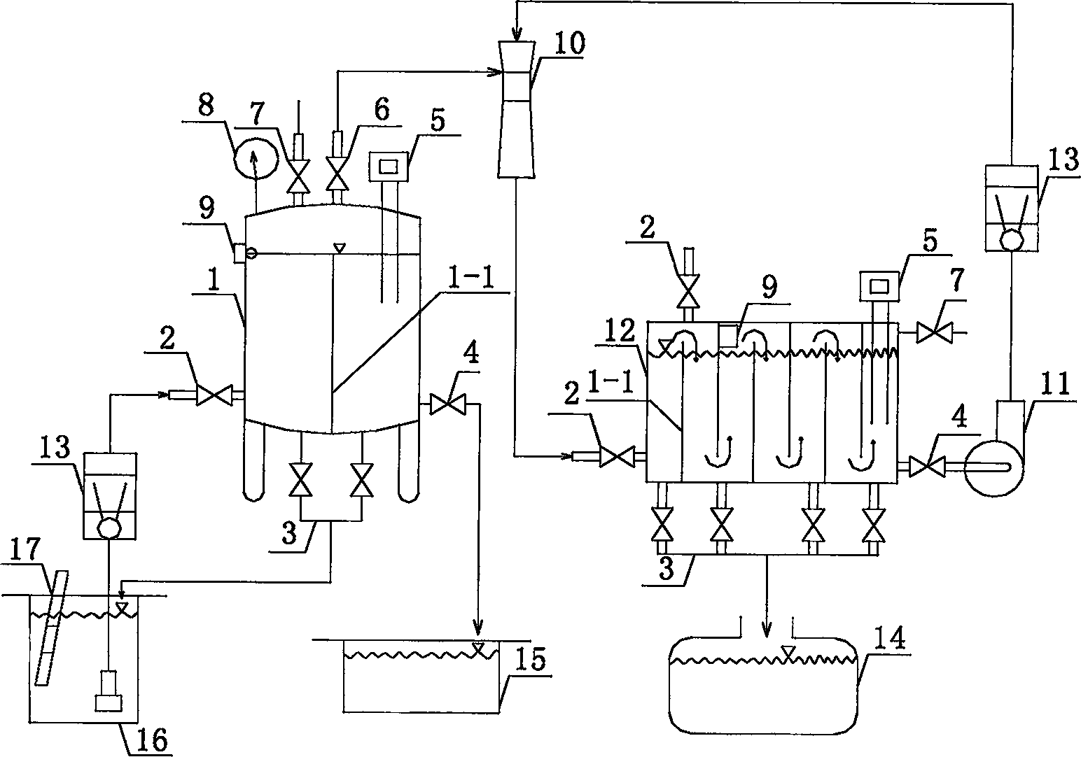
[0068] Example 1. One of the vacuum negative pressure suction denitrification equipment that can be both sequential batch and continuous operation:

[0069] This device combination is typical and simplest, and its structure is as figure 1 As shown: it consists of three parts: vacuum denitrification tank 1, water jet vacuum pump (including water jet 10 and supporting water pump 11) and churning type gas absorption tank 12. The vacuum denitrification tank 1 and the tumbling gas absorption tank 12 are provided with 1 to 60 water flow partitions 1-1 in the tank, or depending on the volume of the vacuum denitrification tank 1 and the tumbling gas absorption tank 12, the water flow The number of baffles increases as the volume increases; if two or more water flow baffles 1-1 are provided, these water flow baffles are arranged in parallel up and down in the tank. Numbers 13 and 14 in the figure are liquid flow meter and ammonia water storage tank respectively.

[0070] The first ty...

Example Embodiment

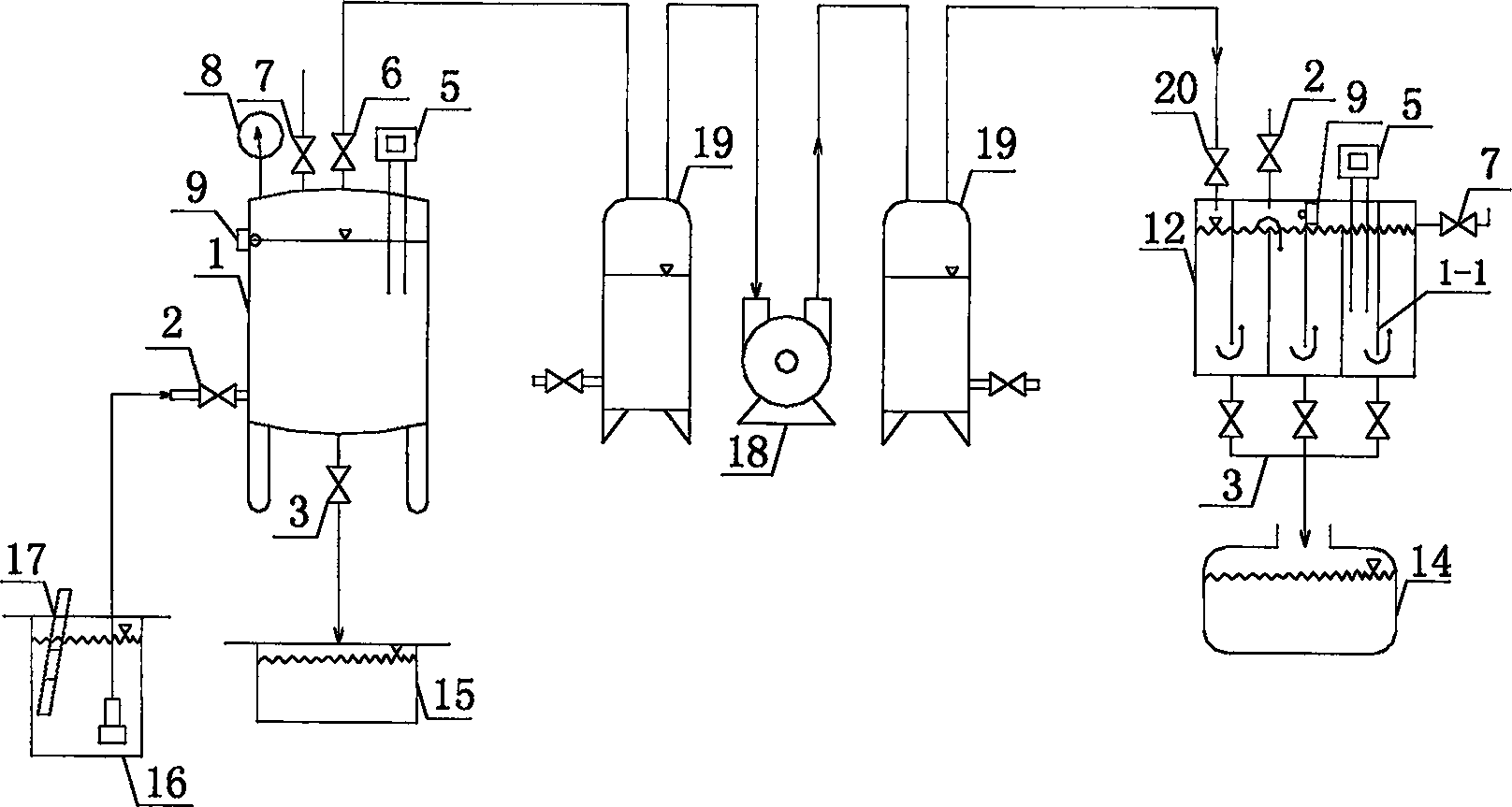
[0074] Example 2. Vacuum negative pressure suction denitrification equipment that can be both sequential batch and continuous operation:

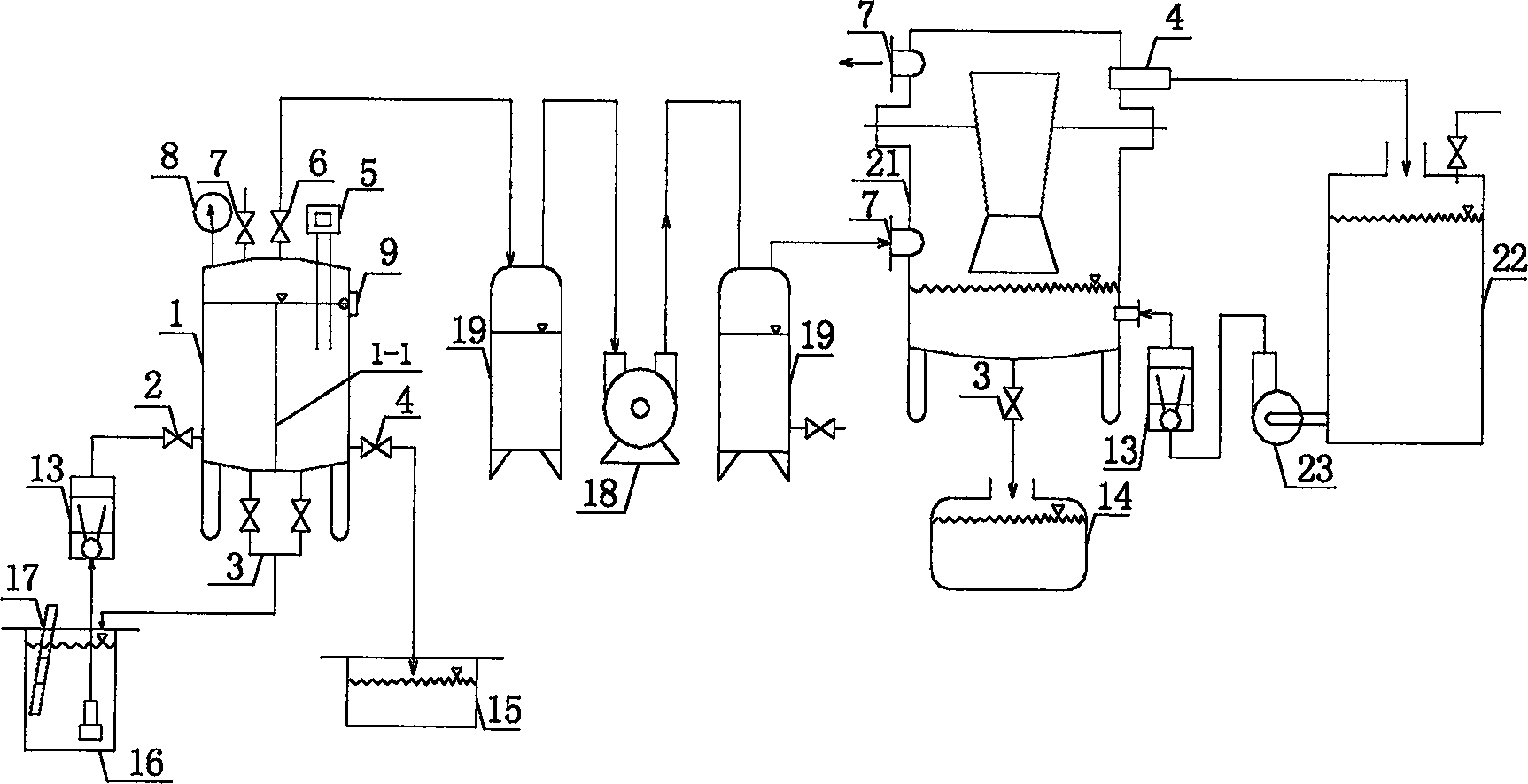
[0075] The structure of this device is as image 3 Shown: Adopt Venturi gas absorption tower 21 to replace figure 1 The churning type gas absorbing tank 12 in adopts water ring type or rotary vane vacuum pump 18 to replace figure 1 water jet vacuum pump. Serial number 22 and 23 among the figure are circulating water tank, circulating water pump respectively. Apart from this, other components including the connection relationship are the same as the first example.

[0076] This equipment carries out vacuum denitrification treatment. The scale of its processing equipment is a continuous flow rate of 4L / h, and the processing time is 1h. The results in Attached Table III can be obtained under different vacuum negative pressures. Compared with Example 1, the denitrification and ammonia regeneration effect of this equipment is slightly worse...

Example Embodiment

[0077] Example 3. The third of the vacuum negative pressure suction denitrification equipment that can be sequenced batch type and can be operated continuously:

[0078] The structure of this device is as Figure 4 As shown: a multi-baffle tumbling vacuum denitrification tank 1 and two tumbling gas absorption tanks 12 (referred to as absorption tanks) are used, and the inner cavity is equipped with a plurality of evenly staggered parallel pipes along the vertical direction of the water inlet and outlet valves. Arranged waterproof current short-circuit partitions, this example is designed as six partitions.

[0079] The connection mode between the jet vacuum suction system of the device and the vacuum denitrification tank 1 and the tumbling gas absorption tank 12 is basically the same as that of the example 1, except that a tumbling gas absorption tank 12 is added. Because a tumbling gas absorption tank 12 is added, the water jet vacuum pump realizes switching between the two ...


PUM


Abstract

This invention provides method and equipment for removing NH3-N from wastewater by vacuum pumping. The equipment comprises a vacuum denitrification tank, a rotational gas absorption tank or a Venturi gas absorption column, and a vacuum pumping system. At least one water flow clapboard is set in the vacuum denitrification tank and the rotational gas adsorption tank, respectively. Besides, a vacuum pumping orifice and a gas-discharging valve are set on the top of the two tank, a water-entering valve and a water-discharging valve are set along both sides of the lower parts, a liquid-emptying valve is set is at the bottom, and a NH3-N concentration sensor and an adjustable autocontroller are set on the bodies. The method and equipment have such advantages as low operation cost and no secondary pollution.

Description

technical field [0001] The invention relates to the field of water treatment, in particular to a vacuum negative pressure suction removal method and equipment for ammonia nitrogen in wastewater. Background technique [0002] Today, the global water pollution situation is increasing day by day, and the eutrophication phenomenon of water body is getting worse and worse. The important reason for the eutrophication of the water body is that domestic and industrial wastewater convert a large amount of NH 3 -N is discharged into the water body. [0003] In domestic wastewater and industrial wastewater, if NH 3 - Low concentration of N (generally less than 200mg / L), can be processed by cheap biological treatment methods. However, in many cases, NH in industrial wastewater 3 -N exceeds 1000mg / L, which contains high concentration of NH 3 -N wastewater will inhibit the growth of microorganisms, so it is not suitable to be directly treated by cheap biological treatment methods, bu...

Claims


Application Information

Patent Timeline
IPC IPC(8): C02F1/20C02F1/58C01C1/02
Inventor 罗亚田
Owner WUHAN UNIV OF TECH
Why Eureka
Try Eureka