Anti-carbon monoxide composite anode electrode catalyst layer structure and preparation method

A technology of electrode catalytic layer and composite anode, which is applied in the direction of battery electrodes, structural parts, circuits, etc., can solve the problems of low utilization efficiency of electrocatalysts, low anti-CO poisoning ability, slow proton migration speed, etc., and achieve fast proton migration speed, Improve utilization rate and strong anti-CO poisoning ability

Active Publication Date: 2006-12-27
SUNRISE POWER CO LTD
View PDF1 Cites 8 Cited by
  • Summary
  • Abstract
  • Description
  • Claims
  • Application Information

AI Technical Summary

Problems solved by technology

[0021] In order to overcome the shortcomings of existing electrodes such as low CO poisoning resistance, short life, slow proton migration speed, and low utilization efficiency of electrocatalysts, the present invention proposes a high-molecular solid electrolyte with strong CO poisoning resistance and a solid polymer electrolyte in the depth direction of the middle catalytic layer. The gradient distribution is easy to control, the proton migration speed is fast, the utilization efficiency of the electrocatalyst is high, the life is long, and the CO / H 2 Anti-CO composite anode catalyst layer for fuel gas proton exchange membrane fuel cell and preparation method

Method used


Image

  • Anti-carbon monoxide composite anode electrode catalyst layer structure and preparation method
  • Anti-carbon monoxide composite anode electrode catalyst layer structure and preparation method
  • Anti-carbon monoxide composite anode electrode catalyst layer structure and preparation method

Examples


Embodiment 1

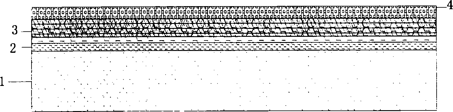
[0046] Such as figure 1 As shown, the anti-CO composite catalytic layer for proton exchange membrane fuel cells of the present invention uses Pt and / or Ru or Au as active components, and its structure is composed of three or more catalytic layers with different functions. The hydrophobic CO primary oxidation layer composed of water agent is the outer catalytic layer, and the hydrophilic electrochemical reaction catalytic layer composed of electrocatalyst and proton conductor is the inner catalytic layer. The partially hydrophobic and partially hydrophilic CO secondary oxidation layer with proton conductor components is the intermediate catalytic layer; the outer catalytic layer is supported by the gas diffusion layer, and the intermediate catalytic layer is located between the outer catalytic layer and the inner catalytic layer. The conductor portion is in contact with the inner catalytic layer, and the other side of the inner catalytic layer is in contact with the proton exch...

Embodiment 2

[0059] 1) Preparation of the outer catalytic layer: use a primary balance to weigh 42.6 mg of 30% Pt / C electrocatalyst, add a small amount of deionized water to completely wet the electrocatalyst, then add 210 mg of XC-72 carbon powder, and then follow (electrocatalyst + carbon powder) 50 times the weight of absolute ethanol and ethylene glycol (25 times each of the two dispersants), ultrasonically oscillating at a frequency of 40KHz for 30 minutes until completely mixed evenly, according to (outer catalytic layer + microporous layer ) 50% of the total weight by adding 10% PTFE emulsion, and continuing to ultrasonically oscillate at a frequency of 40KHz for 30min until uniform to form a slurry. After the prepared slurry was subjected to gel treatment in a constant temperature water margin of 90°C, the slurry was evenly coated on SGL carbon paper using a plastic scraper to obtain an intermediate product; then the prepared above (microporous Layer (MPL)+catalytic layer) intermed...

Embodiment 3

[0065] 1) Preparation of the outer catalytic layer: according to the Ru loading of 0.15mg / cm 2 , (electrocatalyst + carbon powder): dispersant = 1: 40 and (electrocatalyst + carbon powder): PTFE = 7: 3 ratio, using 30% Ru / C electrocatalyst, XC-72 carbon powder, absolute ethanol And three kinds of raw materials of PTFE micropowder, prepare slurry according to the method for step 1) among the embodiment 2. After the prepared slurry was subjected to gel treatment in a constant temperature water margin at 90°C, the slurry was evenly coated on SGL carbon paper using Doctor Blade, and then the prepared above (microporous layer (MPL)+catalytic Layer) is put into roasting furnace, according to step 2) method in embodiment 1, roasting is made to be the outer catalytic layer of substrate with gas diffusion layer;

[0066]2) Prepare the intermediate catalyst layer with the outer catalyst layer as the substrate: according to the ratio of electrocatalyst: dispersant = 1: 30 and electrocat...


PUM

PropertyMeasurementUnit
thicknessaaaaaaaaaa
thicknessaaaaaaaaaa
thicknessaaaaaaaaaa

Abstract

The related preparation method for anti-CO composite positive electrode catalysis layer of proton-exchange member fuel cell comprises: with Pt/C or PtM/C(M is one or more of Ru, Mo, Sn, Ni, Au/Fe2O3,Au/Al2O3, Au/Co2O3, Fe, Co and W) as electric catalyst, a hydrophilic catalyst layer named inner catalyst layer with former catalyst and polymer solid as main components connected to the proton exchange member, a hydrophobic catalyst layer named outer catalyst layer with the catalyst and some hydrophober as main components connected to a diffused layer, and one or more middle catalyst layer with hydrophilic and hydrophobic feather gradient change. This invention has well performances.

Description

technical field [0001] The invention relates to fuel cell technology, in particular to a carbon monoxide (CO) resistant composite anode catalyst layer structure and preparation method for a proton exchange membrane fuel cell. Background technique [0002] In the prior art, the proton exchange membrane fuel cell has the outstanding advantages of high output efficiency and environmental friendliness, and has broad application prospects. It can start at low temperature, has no electrolyte corrosion and leakage, has a simple structure, and is easy to operate. It has a strong competitive advantage in the fields of electric vehicles, regional power stations, spacecraft, and portable power supplies. The development of such underwater deep submersibles is very attractive and has attracted widespread attention in recent years. At present, the energy specific power of proton exchange membrane fuel cells using pure hydrogen as fuel can meet the requirements of the above-mentioned fiel...

Claims


Application Information

Patent Timeline
Patent Type & Authority Applications(China)
IPC IPC(8): H01M4/86H01M4/90H01M4/88H01M8/02H01M8/10
CPCY02E60/521Y02E60/50
Inventor 张华民邱艳玲刘波董明全衣宝廉
Owner SUNRISE POWER CO LTD
Why Eureka
Try Eureka