
Anaerobic carbonization dangerous solid wastes disposing apparatus

A hazardous waste and disposal device technology, applied in incinerators, lighting and heating equipment, combustion methods, etc., can solve the problems of ineffective prevention of dioxin regeneration, dust sticking to cloth bags, tail equipment corrosion, etc., to protect human beings Effects of health, environmental protection, and operating cost savings

Active Publication Date: 2007-01-03
山东盛乙环保科技有限公司
View PDF0 Cites 10 Cited by
  • Summary
  • Abstract
  • Description
  • Claims
  • Application Information

AI Technical Summary

Problems solved by technology

[0006] The purpose of the present invention is to provide an oxygen-free carbonization hazardous solid waste disposal device, which mainly solves the problems of insufficient combustion, black smoke or intermittent black smoke in the existing hazardous solid waste disposal device; it also solves the problem of the existing hazardous solid waste disposal device Due to the poor quenching effect, it cannot effectively prevent the regeneration of dioxins; at the same time, it solves the problem of high humidity in the wet cooling and exhaust smoke of the existing hazardous solid waste disposal device, which causes serious corrosion of the tail equipment, dust sticks to the cloth bag, and increases maintenance costs. question

Method used


Image

  • Anaerobic carbonization dangerous solid wastes disposing apparatus

Examples


Embodiment Construction

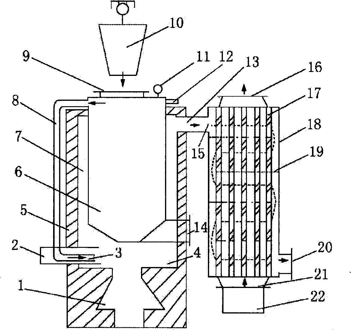
[0030] Examples see figure 1 , the present invention includes anaerobic pyrolysis zone and pneumatic quenching zone.

[0031] The anaerobic pyrolysis zone has a refractory heat preservation shell 5 made of refractory heat preservation material. The lower part of the refractory heat preservation shell 5 is the gas generator 1, the middle part is the combustible gas combustion chamber 4, and the upper part is the furnace fire path 7, the furnace fire path The inside of 7 suspends the pyrolysis tank 6, the top of the pyrolysis tank 6 is equipped with a pressure gauge 11 and a temperature measuring instrument 12, and protrudes from the top of the furnace body 5, and the sealing opening of the top of the pyrolysis tank 6 and the feeding port 9 and the upper feeding Corresponding to the device 10, the top side of the pyrolysis tank 6 communicates with the combustible gas discharge pipe 8, and the combustible gas injection port 3 at the lower end of the combustible gas discharge pipe...


PUM


Abstract

In the invention, a refractory insulated casing is disposed in the anacrobic pyrolyzation zone. A heating furnace is set in the tower part of the casing, a combustible gas combustion chamber is set in the middle part of the casing and in the upper part of the casing there is a hearth fire passage. In the hearth fire passage is suspended a pyrolyzation tank, on top of which a sealed charge door is corresponding to a above feeder and the top is in communication with the outlet pipe of the combustion gas and the bottom of the pyrolyzation tank is connected with a slagging means. On top of the refractory insulated casing is opened a flue outlet insulated casing is opened a flue outlet in communication with a pneumatic quench region, at the bottom of whose casing is set a fan and on its top is set an air-vent.

Description

(1) Technical field [0001] The invention relates to a hazardous solid waste disposal device. (2) Background technology [0002] At present, industrial solid waste and medical waste are mainly disposed of by incineration. The incineration methods mainly include: fixed grate incinerator, mechanical grate furnace, horizontal rotary kiln, vertical oxygen-deficient oxidation furnace, etc. Their common feature is that solid waste is burned directly or indirectly. The rapid cooling and cooling of the above-mentioned incineration flue gas generally adopts wet and semi-dry methods. Practice has proved that the above furnace type incineration and rapid cooling method has the following defects: [0003] 1. Insufficient combustion and black smoke or intermittent black smoke; [0004] 2. The regeneration of dioxin cannot be effectively prevented due to poor quenching effect; [0005] 3. The humidity of the wet cooling and exhaust smoke is high, which causes serious corrosion of the t...

Claims


Application Information

Patent Timeline
Patent Type & Authority Applications(China)
IPC IPC(8): F23G5/027
Inventor 王学江叶孟杰王香玲李冉
Owner 山东盛乙环保科技有限公司
Learn More