Bi-continuous-phase composite friction material of foaming silicon carbide/metal, its member and preparation

A technology of composite friction material and foamed silicon carbide, which is applied in chemical instruments and methods, and other chemical processes, can solve the problems of failure to perform the function of composite material friction parts normally, reducing the mechanical properties and thermal conductivity of materials, and the foam ceramics are prone to damage, etc. problems, to achieve the effect of improving mechanical strength and heat transfer capacity, good designability, enhancing material friction performance and heat resistance

Active Publication Date: 2007-01-17
INST OF METAL RESEARCH - CHINESE ACAD OF SCI
View PDF1 Cites 39 Cited by
  • Summary
  • Abstract
  • Description
  • Claims
  • Application Information

AI Technical Summary

Problems solved by technology

[0010] First, the strength of foam ceramics is low (the compressive strength is generally less than 5MPa), and after forming a composite material with metal, it basically cannot play a load-bearing role.
When rubbing under a relatively high surface pressure, the ceramic foam is easily damaged and cannot normally function as a friction part of the composite material;
[0011] Second, the thermal expa

Method used


Image

  • Bi-continuous-phase composite friction material of foaming silicon carbide/metal, its member and preparation
  • Bi-continuous-phase composite friction material of foaming silicon carbide/metal, its member and preparation
  • Bi-continuous-phase composite friction material of foaming silicon carbide/metal, its member and preparation

Examples


Embodiment 1

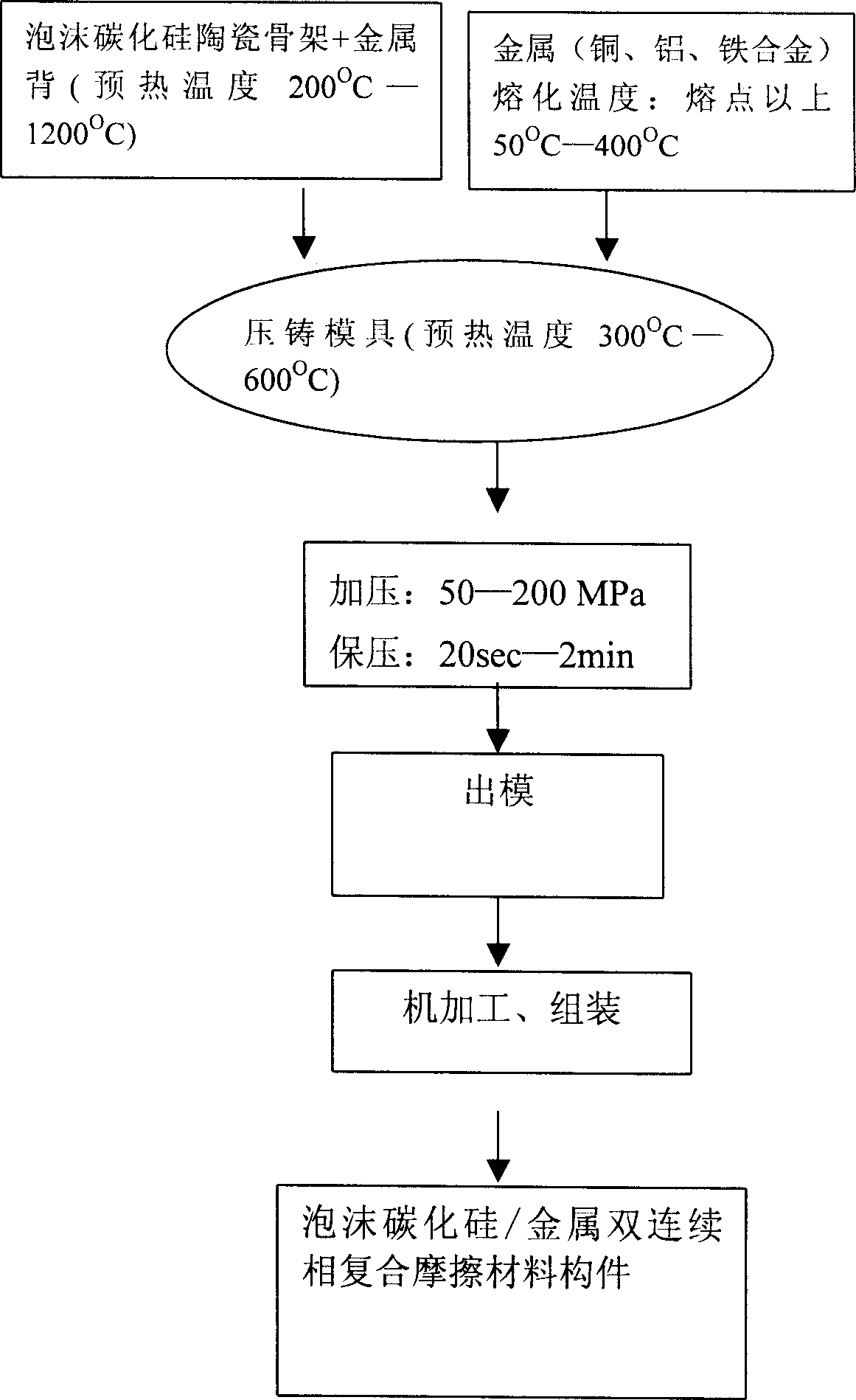
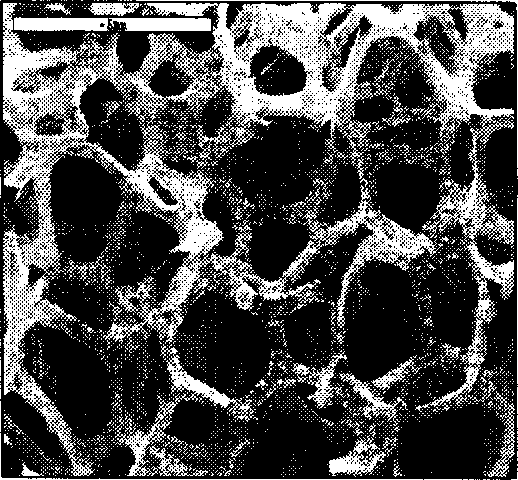
[0101] First prepare the foamed silicon carbide ceramic skeleton according to the method provided by the patent application number 03134039.3, the size is as Figure 8a , Figure 9 . Wherein the thickness of foamed silicon carbide ceramics is 4mm, and the size of the mesh (aperture of foamed silicon carbide ceramics) is 0.5mm. In the foamed silicon carbide ceramics / metal double continuous phase composite material, the volume fraction of foamed silicon carbide ceramics is 15%. The center hole is fixed on the stainless steel mesh of the same size with screws, heated to 300°C and put into a Φ100mm mold.

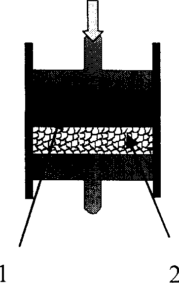
[0102] Using the die-casting method, heat the iron brass Hfe59-1-1 to the melting point (901°C) above 200°C, remove the covering agent, deoxidize, and slag, and then pour it into the mold. The pressure is 50MPa, and the holding time is 20 seconds. Press it into the foamed silicon carbide ceramic skeleton, and machine it to the required size to obtain the foamed silicon carbide...

Embodiment 2

[0104] The difference from Example 1 is:

[0105] Foamed silicon carbide ceramics were prepared according to Example 1. Under the conditions of temperature 1800° C., vacuum 2 Pa, and holding time of 1 hour, the residual silicon inside the framework ribs of the foamed ceramics was removed to obtain porous foamed silicon carbide ceramics. The relative density of porous foam silicon carbide ceramic bars is 90%, the equivalent diameter of pores is 2 μm, and the porosity is 10%.

Embodiment 3

[0107] The difference from Example 1 is:

[0108] Adopt the method for adding pore forming agent (silicon powder) to prepare porous foamed silicon carbide ceramics, in the ceramic slurry prepared by the method provided in the patent application number 03134039.3, according to the formula of the embodiment 1 component in this application Porous foamed silicon carbide ceramics were prepared by adding 20g of silicon powder. The relative density of porous foam silicon carbide ceramic bars is 85%, the equivalent diameter of pores is 10 μm, and the porosity is 15%.


PUM

PropertyMeasurementUnit
Thicknessaaaaaaaaaa
Meshaaaaaaaaaa
Granularityaaaaaaaaaa

Abstract

A foaming silicon carbide/metal double-phase continuous composite friction material, its member and production are disclosed. The composite friction material consists of 15-60% foaming silicon carbide ceramic and 40-85% metal matrix. The procedure is carried out by synthesizing foaming silicon carbide ceramic with metal matrix and combing friction layer with metal layer. It can fulfill friction and bearing functions. It can be used for plane, track train, caterpillar vehicles, wheeled vehicles and ship.

Description

technical field [0001] The invention relates to the preparation technology of friction materials, in particular to a foamed silicon carbide / metal composite friction material with dual continuous phase structure characteristics, its components and its preparation method. Background technique [0002] Friction braking materials are the key materials used in the braking systems of modern vehicles such as aircraft, rail transit trains, tracked vehicles, wheeled vehicles, ships, etc., mainly including C / C composite materials, steel materials (cast iron, cast steel , forged steel), metal matrix composite materials, powder metallurgy materials and semi-metal materials, etc., and are used in the form of friction plates, brake discs, bearing bushes and brake pads. Among them, semi-metallic braking materials are mainly used in the braking system of light vehicles, while other types are mainly used in the braking system of heavy vehicles. With the continuous development of the above-m...

Claims


Application Information

Patent Timeline
IPC IPC(8): C09K3/14
Inventor 张劲松曹小明田冲刘强
Owner INST OF METAL RESEARCH - CHINESE ACAD OF SCI
Why Eureka
Try Eureka