Electronic prompting transfusion device

An infusion set, electronic technology, applied in the direction of instruments, alarms, instruments introduced into the body, etc., can solve the problems of unstable working performance, unreasonable design, high production cost, and achieve stable and reliable working performance, easy to implement, Easy-to-use effects

Inactive Publication Date: 2007-01-24
王宜
View PDF2 Cites 5 Cited by
  • Summary
  • Abstract
  • Description
  • Claims
  • Application Information

AI Technical Summary

Problems solved by technology

[0004] The present invention mainly solves the technical problems existing in the prior art such as complex structure, unreasonable design, high production cost, unstable working performance, and low precision; it provides a method with reasonable design, simple structure, and low production cost. Easy to promote, stable and reliable working performance, high precision electronic prompt infusion set

Method used


Image

  • Electronic prompting transfusion device
  • Electronic prompting transfusion device
  • Electronic prompting transfusion device

Examples


Embodiment 1

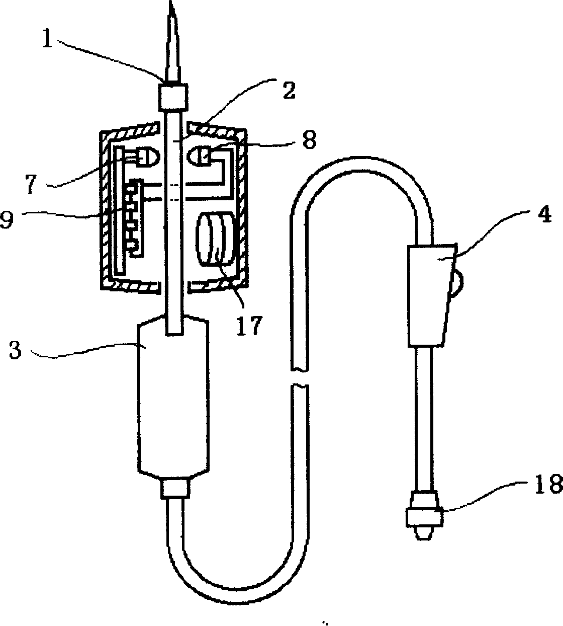
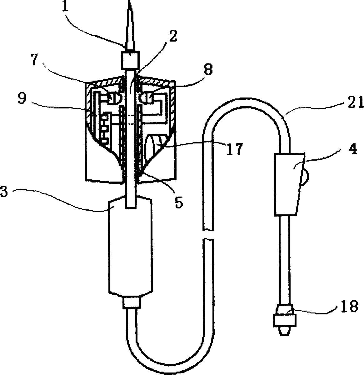
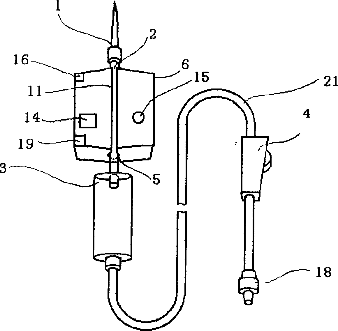
[0026] The electronic prompt infusion set, see Figure 1, Figure 2 and Figure 3 of the description, including the shell cork piercer 1 and the drip hopper 3 are connected through a sufficiently transparent liquid tube 2, and a part of the lower end of the liquid tube 2 is inserted into the drip hopper 3. Form a dropper to ensure that the medicinal liquid forms a clear dripping state in the dropper. The outlet of the dropper is connected to the infusion hose 21, and the flow regulator installed on 21 is connected to the end of 21. The outer conical joint is installed to install the intravenous injection needle. , constitute the medicinal liquid channel of the traditional gravity type disposable infusion set, while the liquid tube 2 passes through the outer shell 6 of the electronic component, and the surface of the shell 6 has a slot 11, and the slot 11 forms a through slot 5 in the shell 6 The liquid supply pipe 2 passes through and is fixed, and on both sides of the inner wall ...

Embodiment 2

[0031] In this embodiment, on the basis of Embodiment 1, the housing 6 is extended downwards, and the extension part is made of a transparent material to form a tubular shape so that it is socketed with the dropping funnel or becomes a part 10 of the upper section of the dropping funnel. The dripping funnel is made of hard material, and the lower section of the dripping funnel must still adopt traditional soft elastic material to maintain the ability to inhale the medicinal liquid into the dripping funnel. The hard upper section of the dripping funnel 10 is equipped with another photodiode 7 and a light-emitting tube 8 to detect For the dripping of the liquid medicine, see the accompanying drawings in the manual, and a trigger timing module is added to the circuit assembly, and each drip triggers the circuit to record the time again. There is no liquid drop detected inside and a prompt is issued, thereby reminding that the liquid level of the liquid medicine has dropped into th...

Embodiment 3

[0033] In this embodiment, on the basis of Embodiment 1, the shape of the housing 6 is further extended downwards to partially enclose the dripping funnel 3, and a notch 12 is formed beside the dripping funnel to accommodate the protruding upper end of the dripping funnel, see the manual Accompanying drawing, be provided with another photosensitive diode 7 and luminescent tube 8 to detect the dripping of liquid medicine wherein, beside the liquid pipe in the upper casing, still retain a pair of original photosensitive tube 7 and luminous tube 8 beside the dropping funnel 3, The rest are similar to those in Embodiment 2, and will not be repeated here.


PUM


Abstract

The present invention relates to medical equipment, and is especially one improved transfusion device with electronic prompt. The transfusion device with electronic prompt includes a bottle plug puncture unit, a dropping funnel, a liquid pipe connected between the puncture unit and the dropping funnel, a regulator, an optoelectronic sensor and a processing circuit connected to the sensor. It features the LED and the photosensitive tube set beside the liquid pipe and connected to the processing circuit. The present invention has the advantages of simple structure, performance stability, timely informing, etc.

Description

technical field [0001] The invention relates to a medical device, in particular to a structural improvement of an electronic prompt infusion set. Background technique [0002] When infusion, the most commonly used in hospitals is the very simple, effective and cheap gravity-type disposable infusion set with Murphy dropper and flow regulator, but when the infusion is almost finished, the general patient or accompanying staff should pay attention to the remaining amount of medicine from time to time. , often there is still a considerable amount of liquid medicine to change the medicine bottle. If you want to automatically remind patients and medical staff when the medicine is finished, you can use a more complicated and expensive pump-driven infusion device or an electric injector, and there are also infusion alarm solutions that use the spring scale principle. The Chinese patent document discloses an infusion prompter (application number: 200420035277.X), in which a prompt c...

Claims


Application Information

Patent Timeline
Patent Type & Authority Applications(China)
IPC IPC(8): A61M5/14G08B21/00
Inventor 王宜
Owner 王宜
Why Eureka
Try Eureka