Ceramic honeycomb filter

A ceramic honeycomb and filter technology, which is applied to machines/engines, mufflers, engine components, etc., can solve the problems of rising pressure drop, cumbersomeness, and smaller flow passages on the inflow side of the filter to achieve the effect of low pressure drop.

Inactive Publication Date: 2007-01-24
HITACHI METALS LTD +1
View PDF2 Cites 6 Cited by
  • Summary
  • Abstract
  • Description
  • Claims
  • Application Information

AI Technical Summary

Problems solved by technology

If the accumulation of particles becomes larger, the flow path on the inflow side will become smaller, and the pressure drop of the filter will increase.
Ultimately reduces particle collection time and necessitates cumbersome filter regeneration

Method used


Image

  • Ceramic honeycomb filter
  • Ceramic honeycomb filter
  • Ceramic honeycomb filter

Examples


Embodiment 1 and 2

[0075] Embodiment 1 and 2, reference example 1

[0076] For the manufacture of SiO with a mass of 49-51% 2 , 35-37% Al by mass 2 o 3 And cordierite, which is mainly composed of MgO with a mass of 13-15%, needs to be quantitatively mixed with kaolin powder, pseudo-fired kaolin powder, alumina powder, aluminum hydroxide powder, silica powder and talc powder to add binder and lubricant respectively And spherical resin powder used as a pore-forming agent. Water is added to the resulting mixture to make a plasticizable dosing mixture. The quantitative mixture is pressed into a cylindrical honeycomb and dried.

[0077]

Porogen

The average particle size

(μm)

20-100μm particles

Diameter ratio (mass%)

Example 1

64

75

Example 2

62

62

Example 3

52

48

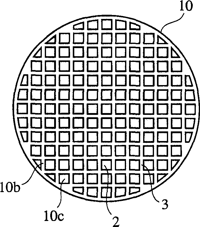
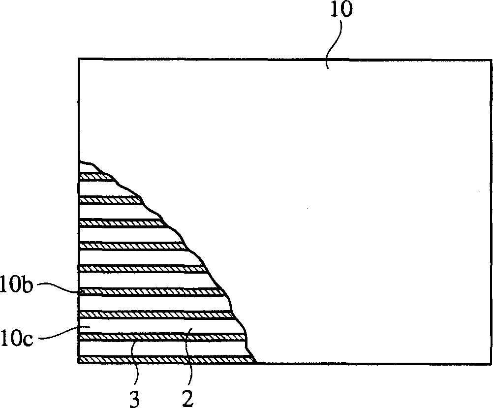
[0078] The resulting molded body was sintered at a temperature of 1350-1440° C., as shown in FIG. 1 , to produce various...

Embodiment 3-7

[0098] Make the same plasticized quantitative mixture as in Example 1, and use the extrusion molding method to make a cylindrical honeycomb structure from the quantitative mixture. In order to obtain various wall thicknesses and every 1cm 2 The number of runners adjusted the size of the forming die. Each molded body was sintered at a temperature of 1350-1440° C. to produce the cordierite honeycomb structures of Examples 3-7 having various porous partition walls and through holes. The diameter of each honeycomb structure is 143mm, the length is 152mm, and the thickness of the partition wall is 0.15-0.33mm, every 1cm 2 The number of runners is 39-62. In addition, the porosity of each honeycomb structure was 65%, the average pore diameter was 20.8%, and the maximum value of the gradient Sn of the cumulative pore volume distribution curve was 1.12.

[0099] Both ends of the filter were sealed in the same manner as in Example 1 to produce a cordierite honeycomb filter. In the s...

Embodiment 8 and Embodiment 9

[0101] Embodiment 8 and embodiment 9, reference example 2

[0102] As a ceramic material with a high proportion surface area, activated alumina powder and alumina glue with a central particle diameter of 5 μm are mixed into water to obtain activated aluminum powder slurry. As in Examples 1 and 2 and Reference Example 1, this slip was coated on a ceramic honeycomb structure. After removing excess slurry, apply it repeatedly, and finally apply 60g / L activated aluminum to the honeycomb structure. The honeycomb structure was dried at 120°C and then sintered at 800°C. Further, the honeycomb structure was immersed in a platinum chloride hydroxide solution, dried at 120°C, and then fired at 800°C. A ceramic honeycomb filter with about 2 g / L of platinum catalyst was thus produced.

[0103] The same method as in Example 1 was used to measure the pressure drop of the ceramic honeycomb filter with platinum catalyst. The pressure drop of the ceramic honeycomb filter with platinum cata...


PUM

PropertyMeasurementUnit
thicknessaaaaaaaaaa
densityaaaaaaaaaa
porosityaaaaaaaaaa

Abstract

A ceramic honeycomb filter, which is composed of a ceramic honeycomb structure with a porous partition wall that divides a plurality of flow channels, and uses exhaust gas to pass through the porous partition wall to filter out particles in the exhaust gas, wherein the sealing of the specified flow channel At the end, the porous partition is provided with a catalyst, and in the case of measuring the porous partition by mercury porosimetry, the porosity is 60-75% and the average pore diameter is 15-25 μm, relative to the nth measurement The maximum value of the gradient Sn of the cumulative pore volume distribution curve of the pore diameter of the point is above 0.7, and the gradient Sn of the cumulative pore volume distribution curve is expressed by the following formula (1): Sn=-(Vn-Vn-1) / [ logDn-log(Dn-1)] (1), (where: Dn is the pore diameter (μm) of the nth measuring point, Dn-1 is the pore diameter (μm) of the n-1th measuring point, Vn is the cumulative pore volume (cm3 / g) of the nth measuring point, and Vn-1 is the cumulative pore volume (cm3 / g) of the n-1th measuring point).

Description

[0001] This application is a divisional application of the invention patent application named "ceramic honeycomb filter" and application number 02154555.3 submitted by Hitachi Metals Co., Ltd. and Hino Automobile Co., Ltd. on September 13, 2002. technical field [0002] The invention relates to a ceramic honeycomb filter for filtering particles contained in exhaust gas of a diesel engine. Background technique [0003] In order to filter the particulates emitted by diesel engines, a ceramic honeycomb filter with porous partition walls is being studied to filter the exhaust gas containing particulates through the partition walls. Such filters are generally referred to as particulate collection filters (diesel particulate filters). Fig. 2 (a) is the front view of the ceramic honeycomb filter 11 used as a particle collection filter, and Fig. 2 (b) is a sectional side view of this part, image 3 It is a schematic sectional view of the ceramic honeycomb filter 11 shown in FIG. 2 ....

Claims


Application Information

Patent Timeline
Patent Type & Authority Applications(China)
IPC IPC(8): F01N3/022
Inventor 诹访部博久大坪靖彦德丸慎弥舟桥博中込惠一辻田诚通阪久贵
Owner HITACHI METALS LTD
Why Eureka
Try Eureka