

Method and equipment for pyrogenic decomposition and carbonisation of urban garbage
A technology for pyrolysis carbonization and municipal waste, applied in the field of environmental protection, can solve problems such as large fuel consumption, and achieve the effect of avoiding operational problems, good social and environmental benefits, and saving fossil fuels
- Summary
- Abstract
- Description
- Claims
- Application Information
AI Technical Summary
Problems solved by technology
Method used
Image

Examples
example 1
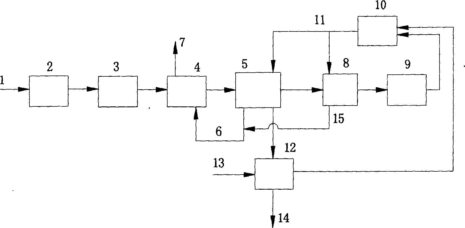
[0020] Example 1: if figure 1 As shown, after municipal solid waste 1 is collected to the disposal site, sorting machine 2 is used to sort out the combustible components of the waste, and then it is crushed to 10 mm by crusher 3 and sent to dryer 4 . The waste flue gas 6 discharged from the jacket of the pyrolysis carbonization furnace 5 is passed into the drying device 4 to directly contact with the garbage for heating. After deodorization (deodorization device is not shown), it is vented. The dried garbage enters the pyrolysis and carbonization furnace 5, and the garbage is firstly pyrolyzed at 250°C in the first stage, and then enters the second stage of the pyrolysis and carbonization furnace for dechlorination and pyrolysis at 350°C. The pyrolysis gas discharged from the pyrolysis and carbonization furnace 5 enters the pyrolysis gas heater 8 and is heated by part of the high-temperature gas discharged from the burner. After raising the temperature by 10-50°C, it enters ...
example 2
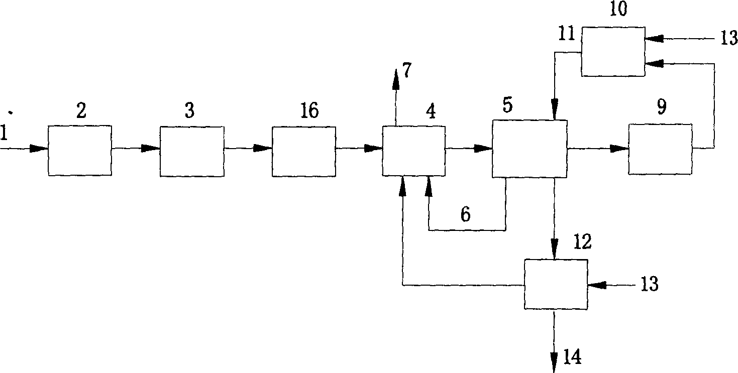
[0021] Example 2: if figure 2 As shown, after the municipal solid waste is collected to the disposal site, it is sorted by a sorting machine to sort out the combustible components of the waste, and then crushed by the crusher 3 to a size of 10 mm. Further, after it is squeezed to remove moisture therein with a press machine 16, the waste flue gas 6 discharged from the input drying device 4 and the jacket of the pyrolysis furnace 5 and the hot air discharged from the carbonized solid fuel storage tank are directly contacted for drying. The temperature of the exhaust gas 7 discharged from the device 4 is controlled between 80-140°C and discharged. The dried garbage enters the pyrolysis and carbonization furnace 5, dechlorination and pyrolysis at 480°C, the pyrolysis gas enters the acid remover 9 to remove the acid gas in the gas, and then enters the burner 10 to mix with air 17 for combustion. The gas 11 enters the jacket of the pyrolysis and carbonization furnace 5 to indirec...
example 3
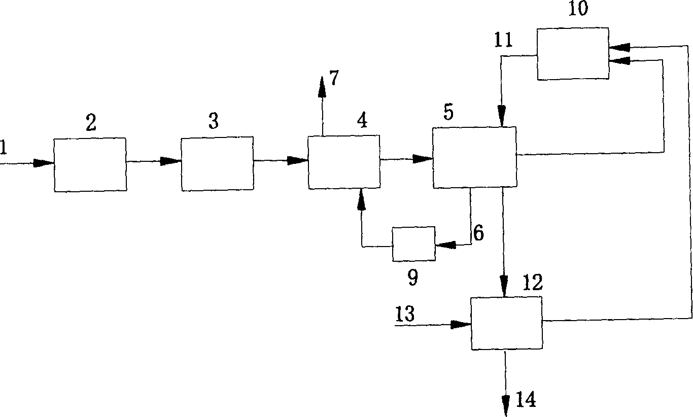
[0022] Example 3: if image 3As shown, after municipal solid waste 1 is collected to the disposal site, sorting machinery is used to sort out the combustible components of the waste, and then the crusher 3 is used to crush it to 5mm. Then input drying device 4, with the waste flue gas 6 discharged from the jacket of pyrolysis carbonization furnace 5, after the acidic substance in the gas is removed by the acid remover 9, directly contact and dry as the heat source gas for drying, and the waste gas 7 discharged from the heater The temperature is controlled between 80-150°C. The dried garbage enters the pyrolysis carbonization furnace 5 for dechlorination and pyrolysis at 450°C. The pyrolysis gas discharged from the pyrolysis and carbonization furnace 5 enters the burner 10 through an insulated pipeline and mixes with the heated air discharged from the solid fuel storage tank for combustion. The high-temperature gas 11 generated by combustion enters the jacket of the pyrolysis...
PUM
 Abstract
Description
Claims
Application Information