Film forming method

A film-forming method and film-forming technology, used in gaseous chemical plating, coatings, electrical components, etc., can solve problems such as poor step coverage, and achieve the effects of reducing impurities, increasing film-forming speed, and improving quality

Inactive Publication Date: 2007-01-31
TOKYO ELECTRON LTD
View PDF1 Cites 6 Cited by
  • Summary
  • Abstract
  • Description
  • Claims
  • Application Information

AI Technical Summary

Problems solved by technology

[0006] However, in this way, the source gas and H as a reducing gas are supplied at the same time 2 gas, make it plasma, and then supply the method of reducing gas, in which the raw material gas and H 2 Film formation is performed when gas plasma is used, but there is a problem of poor step coverage because these cannot reach the bottom of the micropores

Method used


Image

  • Film forming method
  • Film forming method

Examples


Embodiment Construction

[0031] Various preferred embodiments of the present invention will be described below with reference to the accompanying drawings.

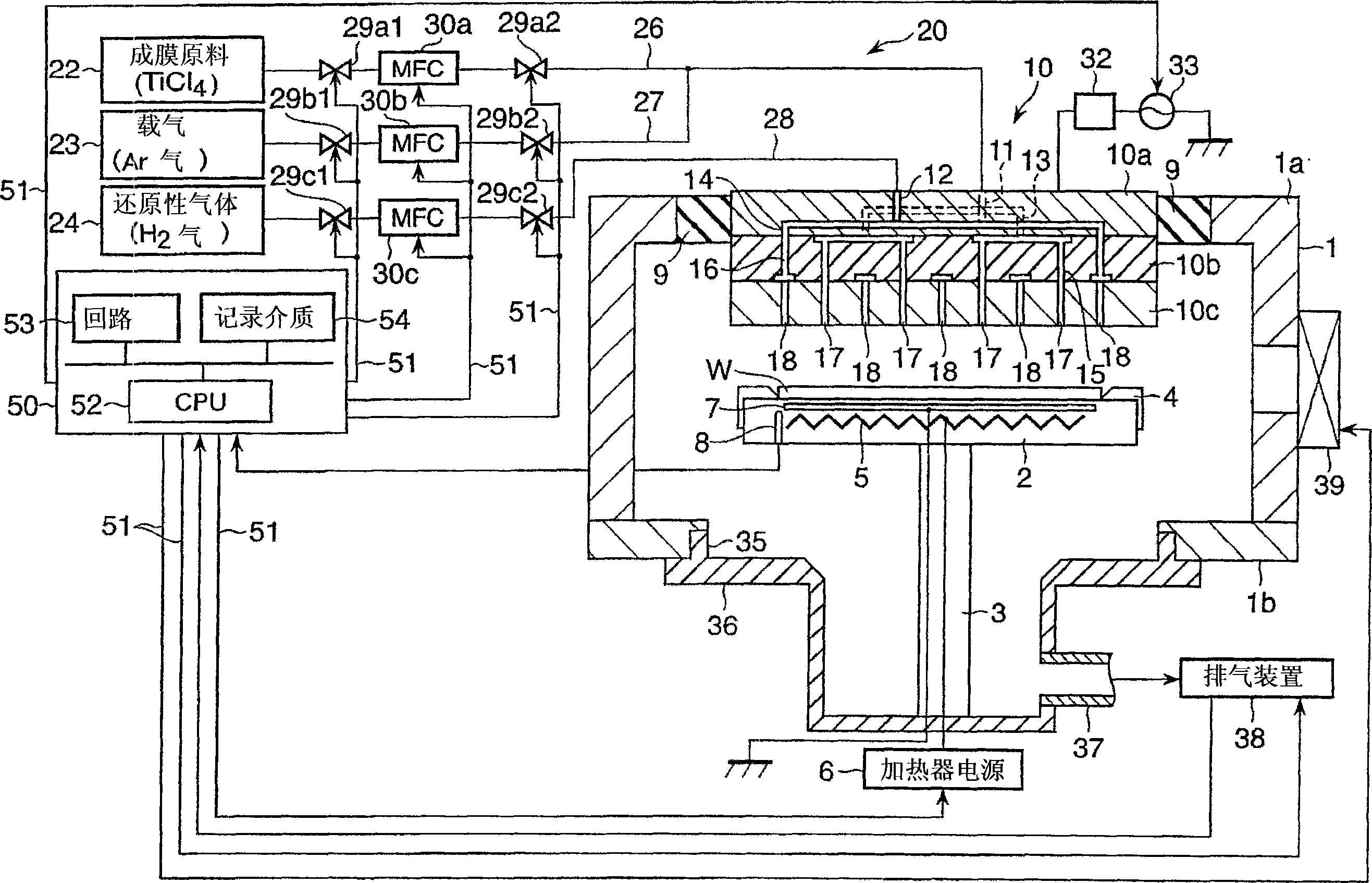
[0032] Such as figure 1 As shown, various functional elements of the film forming apparatus 10 of this embodiment are connected to a control computer 50 that automatically controls the operation of the entire film forming apparatus via a signal line 51 . Here, the so-called functional requirements include heater power supply 6, valves 29a1-29c2, mass flow controllers (MFC) 30a-30c, high-frequency power supply 33, exhaust device 38, gate valve 39 and other peripheral devices. All the elements for operating in the apparatus 10 to realize predetermined film-forming process conditions. Here, only a part of the many signal lines 51 is illustrated for convenience. The control computer 50 is a typical general-purpose computer that can realize arbitrary functions depending on the software it runs.

[0033] The control computer 50 has a central computi...


PUM


Abstract

A film forming method is provided for forming a thin film including a metal on a substrate by alternately supplying the substrate with a film forming material including the metal and a reducing gas. At least a part of the film forming material is dissociated or decomposed in vapor phase by plasma and supplied onto the substrate.

Description

technical field [0001] The present invention relates to a method for forming metal thin films such as metal films and metal nitride films, and in particular to the formation process of metal nitride films and metal films used in semiconductor device circuits. Background technique [0002] In the wiring process of a semiconductor integrated circuit, it is required to form a barrier film in order to suppress the diffusion of a Cu film into a low dielectric constant interlayer insulating film (low-k film). It is expected to see TiN, TaN, WN, Ti, Ta, W, etc. among the materials of the barrier film. [0003] S.M.Rossnagel et al, Plasma-enhanced atomic layer deposition of Taand Ti for Interconnect diffusion barriers.J.VacSci.Technol.B 18(4), Jul / Aug 2000. As a film-forming method for metal thin films (such as Ti films), It is recorded that the raw material gas uses TiCl 4 , reducing gas using H 2 , the PE-ALD (Plasma Enhanced-Atomic Layer Deposition: Plasma Enhanced-Atomic Laye...

Claims


Application Information

Patent Timeline
Patent Type & Authority Applications(China)
IPC IPC(8): C23C16/455C23C16/515H01L21/28H01L21/285H01L21/768
CPCH01L21/28562C23C16/515C23C16/45542H01L21/76841C23C16/45553C23C16/4408
Inventor 吉井直树小岛康彦
Owner TOKYO ELECTRON LTD
Why Eureka
Try Eureka