Gas-liquid dissolution apparatus
A gas-liquid dissolving, gas-liquid technology, applied in the directions of dissolving, dissolving, water aeration, etc., can solve problems such as the inability to effectively increase the oxygen concentration, and achieve the effects of increasing durability, expanding contact area, and increasing contact opportunities
- Summary
- Abstract
- Description
- Claims
- Application Information
AI Technical Summary
Problems solved by technology
Method used
Image
Examples
no. 1 example
[0100] Embodiments of the present invention will be explained below with reference to the drawings.
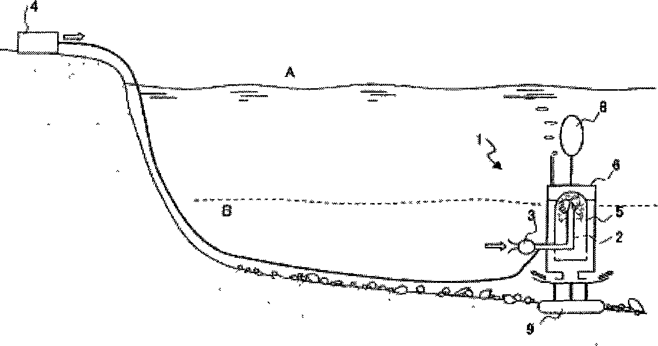
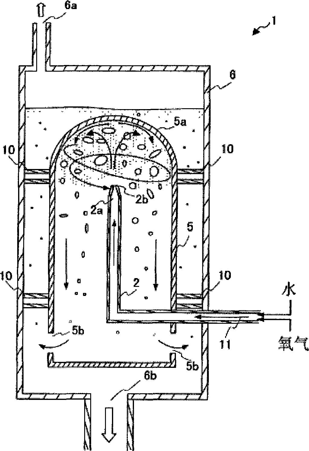
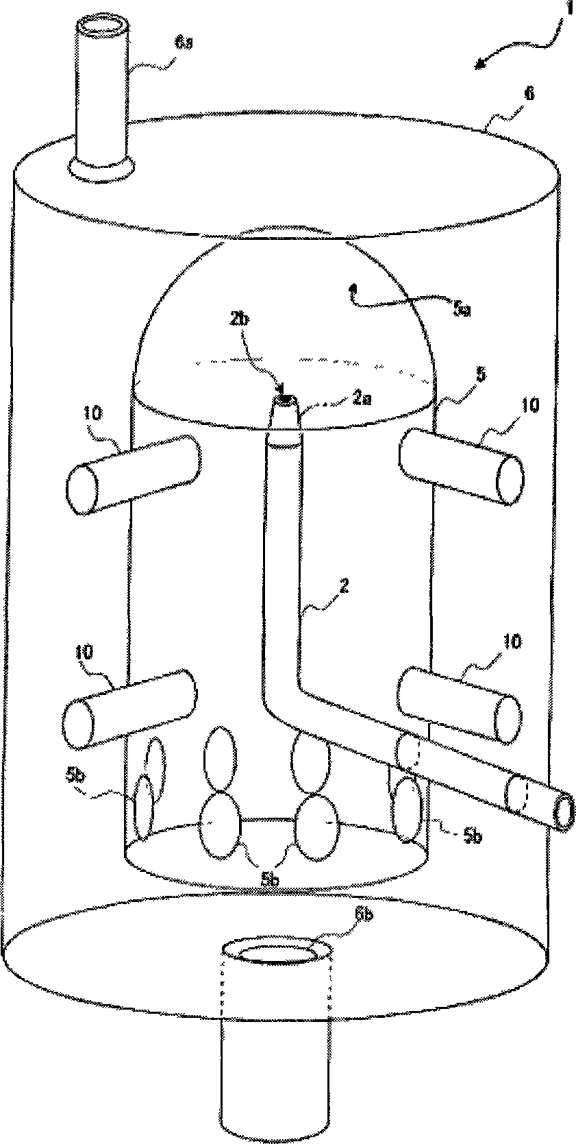
[0101] figure 1 It is a schematic diagram of using the gas-liquid dissolving device described in this example to improve an anoxic lake. figure 2 It is a cross-sectional view of the main configuration parts of the gas-liquid dissolving device according to this embodiment. image 3 It is an oblique schematic view of the main parts of the gas-liquid dissolving device according to this embodiment. The gas-liquid dissolving device 1 includes a pump 3 for extracting water in the anoxic water area B of the lake A, and provides the extracted water to the nozzle 2, and an oxygen supply unit 4 for supplying gas containing oxygen (hereinafter, The air used is replaced by "oxygen") to the nozzle 2, a nozzle 2 for spraying the water provided by the pump 3 and the oxygen provided by the oxygen supply unit 4 to the separation plate 5a in the gas-liquid dissolving chamber, and a gas-liqui...
no. 3 example
[0118] The gas-liquid dissolution device for treating seawater will be introduced below. If the gas-liquid dissolving device according to the first embodiment works in areas containing salt in seawater, or in areas with high salinity in seawater, relatively small air bubbles will be generated, and will form in the gas-liquid separation chamber. The phenomenon that sea water is difficult to separate from air bubbles appears in the water. This is due to the fact that the salt will create tiny air bubbles, which will give buoyancy to even a small column of water. In the third embodiment, it will be explained how the gas-liquid dissolving device separates air bubbles and seawater by using a circulating water column.
[0119] Figure 7 It is a sectional view of the main configuration part of the gas-liquid dissolving device according to the third embodiment. Figure 8 It is a cross-sectional view of the gas-liquid dissolution chamber including through holes. The gas-liquid diss...
no. 4 example
[0130] In the fourth embodiment, the nozzle of the device ejects the gas-liquid multiphase liquid under the action of normal suction. Figure 9 It is a schematic diagram of the nozzle top of the gas-liquid dissolving device according to the fourth embodiment. According to the gas-liquid dissolving device of the present embodiment, the gas supply pipe 34 communicates upwardly through the nozzle 32 with a position on the surface where the injection port 32b is provided. The nozzle 32 is tapered toward the spray port 32 b such that water is forced to be sprayed from the nozzle 32 . At the same time, a pressure difference is generated, and air is sucked from the air supply pipe 34 , and finally the liquid ejected from the nozzle 32 is a gas-liquid multiphase liquid.
[0131] According to the above structure, air can be supplied through the other end of the air supply pipe 34 located on the water surface without supplying air by a pump. Due to the influence of air pressure, the i...
PUM
| Property | Measurement | Unit |
|---|---|---|
| composition ratio | aaaaa | aaaaa |
Abstract
Description
Claims
Application Information
 - R&D
- Intellectual Property
- Life Sciences
- Materials
- Tech Scout
- Unparalleled Data Quality
- Higher Quality Content
- 60% Fewer Hallucinations
Browse by: Latest US Patents, China's latest patents, Technical Efficacy Thesaurus, Application Domain, Technology Topic, Popular Technical Reports.
© 2025 PatSnap. All rights reserved.Legal|Privacy policy|Modern Slavery Act Transparency Statement|Sitemap|About US| Contact US: help@patsnap.com


