
Pipe type continuously reacting apparatus

A chemical reaction and tube-type technology, applied in the field of tube-type continuous reaction devices, can solve problems such as large latent heat of gasification of liquefied gas raw materials, accelerated feeding, and poor control, so as to reduce side reactions, reduce production energy consumption, The effect of eliminating adverse effects

Inactive Publication Date: 2007-03-14
左德兴 +1
View PDF0 Cites 17 Cited by
  • Summary
  • Abstract
  • Description
  • Claims
  • Application Information

AI Technical Summary

Problems solved by technology

The disadvantage is that the latent heat of vaporization of the liquefied gas raw material is very large, and it needs to be heated and vaporized before entering the reactor. During the esterification reaction, a large amount of heat needs to be released when the reaction raw material is converted from a gaseous state to a liquid state. This heat needs to be cooled by a heat exchange device. High energy consumption and low efficiency
Moreover, the raw materials in the reaction kettle have different concentrations in the early, middle, and late stages of the reaction process, which can easily cause high raw material concentrations in the early stage of the reaction, violent reactions, and poor control. The reaction is stable in the middle stage of the reaction. The concentration of raw materials is low, the reaction is slow, and the heat release is small. In order to control the temperature in the reactor, it is often necessary to speed up the feeding, resulting in the accumulation of raw materials in the reactor, long holding time in the later stage, and low utilization of equipment.

Method used


Image

  • Pipe type continuously reacting apparatus
  • Pipe type continuously reacting apparatus

Examples


Embodiment Construction

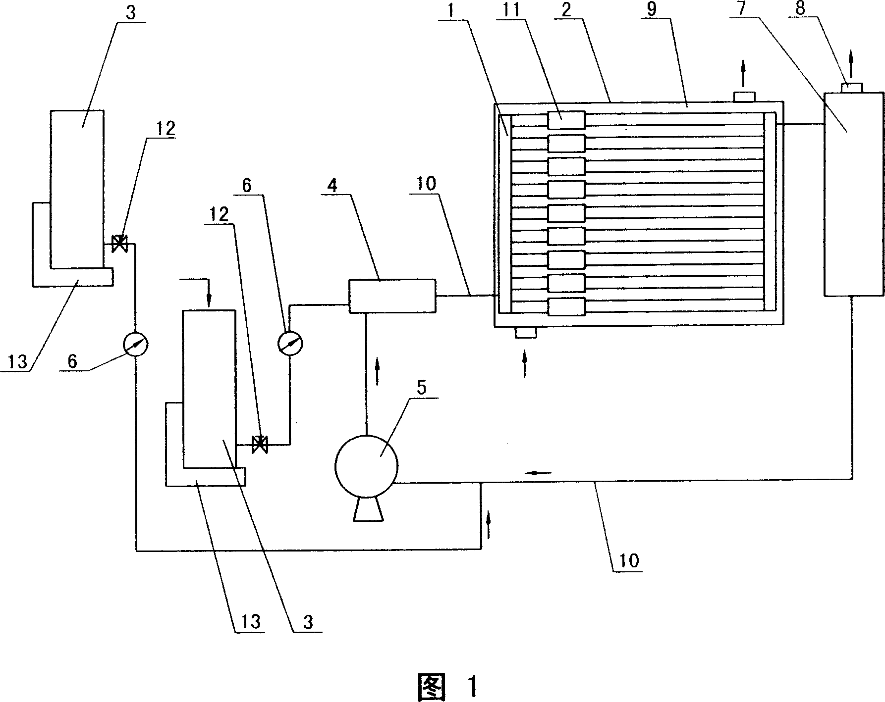
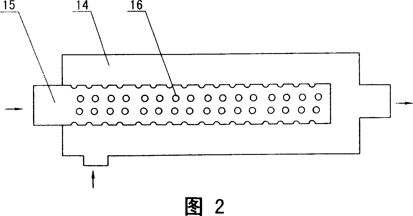
[0015] 1. Reactor 2, heat exchanger 3, raw material tank 4, pre-mixer 5, circulation pump 6, flow controller 7, buffer tank 8, outlet 9, cooling medium 10, pipeline 11, static mixer 12, valve 13 , measuring scale 14, round tube 15, thin tube 16, small hole

[0016] Fig. 1~2 is the embodiment that the present invention adopts the reaction of ethylene oxide and phosphorus trichloride to generate tris (2-chloroethyl) phosphite. The reactor 10 adopts a tubular reactor, the static mixer 11 is connected in series in the reaction tube, and placed in the heat exchanger 2 filled with the cooling medium 9, the pre-mixer 4 includes a circular tube 14 with both ends blocked and a set The narrow tube 15 fixed in the round tube 14, the end of the thin tube 15 is blocked, and the small holes 16 with a diameter of 0.5-1mm are evenly distributed on the tube wall, and the head end passes through the round tube 14, and passes through the flow controller 6 Connect the outlet of the ethylene oxid...


PUM


Abstract

The invention relates to a tubular continuous reactor, which comprises reactor, heat exchanger and material pot used to contain materials. Wherein, it is characterized in that: it also comprises pre-mixer, circulate pump and flux controller; said mixer is tubular and mounted inside the heat exchanger, while its input via pre-mixer is connected to the output of circulate pump and the outlet of material pot with flux controller; the outlet of tubular reactor is connected to the buffer pot whose top has product outlet and bottom has input connected to another outlet of material pot with flux controller to connect the circulate pump; before reaction, the system is filled with final products, then start the circulate pump and material valve, via the power of circulate pump, the reaction materials are mixed by pre-mixer, to enter into tubular reactor to process esterification; and part of product will enter into thermal-insulated pot via the outlet of buffer pot to be stored, and another part enters into circulate pump to be stored in reactor.

Description

Technical field [0001] The invention provides a tubular continuous reaction device, which belongs to the technical field of esterification reaction. Background technique [0002] The traditional esterification reaction device mostly includes a liquid raw material metering device, a reactor with a dynamic agitator, a heat exchange device, a liquefied gas raw material vaporization tank, and a metering device. The gas raw material is subjected to bubbling absorption esterification reaction in the reactor. The disadvantage is that the latent heat of vaporization of the liquefied gas raw material is very large, and it needs to be heated and vaporized before entering the reactor. During the esterification reaction, a large amount of heat needs to be released when the reaction raw material is converted from a gaseous state to a liquid state. This heat needs to be cooled by a heat exchange device. High energy consumption and low efficiency. Moreover, the raw materials in the react...

Claims


Application Information

Patent Timeline
Patent Type & Authority Applications(China)
IPC IPC(8): B01J14/00C07F9/141
Inventor 左德兴浦伟祖
Owner 左德兴
Learn More