Intelligent computers group monitoring method
A monitoring system and cluster technology, applied in transmission systems, hardware monitoring, digital transmission systems, etc., can solve problems such as the inability to realize the monitoring of disk arrays and switches in the cluster system, and the inability to implement switching operations, so as to achieve safe operation and reduce the amount of transmission. , to ensure the effect of complete extraction
- Summary
- Abstract
- Description
- Claims
- Application Information
AI Technical Summary
Problems solved by technology
Method used
Image
Examples
Embodiment 1
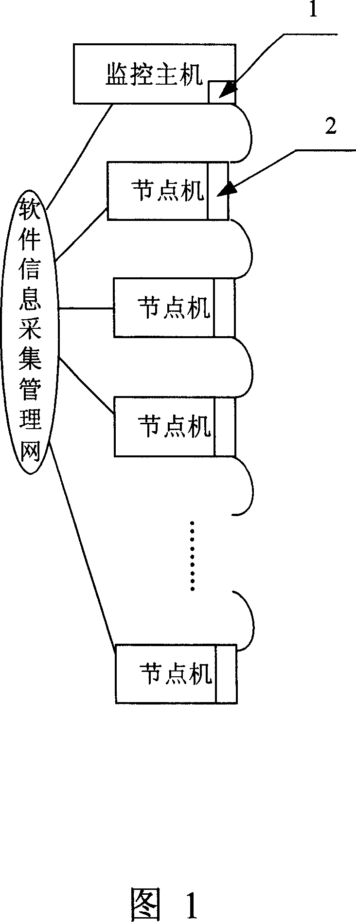
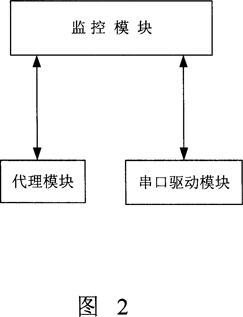
[0028] This embodiment is a preferred implementation of the present invention. FIG. 1 is a schematic diagram of the hardware connection structure of the cluster monitoring system of the present invention, and FIG. 2 is a schematic diagram of data flow of software modules of the cluster monitoring system of the present invention. As shown in Fig. 1 and Fig. 2, the present invention comprises monitoring host computer, node machine, software information acquisition management network, acquisition card, node card, monitoring module, agent module, monitoring host computer and each node machine are mutually connected by management network; As shown in Fig. 1, the acquisition card 1 is arranged on the monitoring host, and the node card 2 is arranged on each node machine, and the acquisition card and the node cards are connected in a daisy chain mode through a network cable to form an acquisition hardware information management network, and collect and transmit hardware information; As...
Embodiment 2
[0033] This embodiment is a further preferred implementation of the present invention. Compared with Embodiment 1, the monitoring of disk arrays and switches is added in the cluster monitoring system. FIG. 3 is a schematic diagram of the hardware connection structure of the cluster monitoring system containing disk arrays and switches. , as shown in Figure 3, the entire cluster monitoring system includes a disk array and a switch; Figure 4 is a schematic diagram of the data flow of the software module of the cluster monitoring system including a disk array and a switch, as shown in Figure 4, the monitoring module is in the SNMP protocol Layer access switches and disk arrays, the disk array support module collects the following disk array information: disk array serial number, CPU type, cache capacity, IP address, number of disks, number of logical disks, number of logical volumes, logical disk ID, logical Disk capacity, RAID type, logical disk online status, disk capacity, SCSI...
Embodiment 3
[0035] This embodiment is a further preferred implementation of the present invention. Compared with Embodiment 2, in the process of monitoring information processing, a monitoring information database is added to realize mass storage of monitoring data and evaluation of historical monitoring information. FIG. 5 is Schematic diagram of the data flow of the cluster monitoring system software module with the monitoring information database, as shown in Figure 5, the monitoring module writes the software information, hardware information, switch information or / and disk array information collected in real time to the monitoring information database, or reads Software information, hardware information, switch information or / and disk array information in the monitoring information database. In this embodiment, a monitoring information database is established locally to store static information, real-time dynamic information and historical dynamic information. Only the latest data is ...
PUM
 Abstract
Description
Claims
Application Information
 - R&D
- Intellectual Property
- Life Sciences
- Materials
- Tech Scout
- Unparalleled Data Quality
- Higher Quality Content
- 60% Fewer Hallucinations
Browse by: Latest US Patents, China's latest patents, Technical Efficacy Thesaurus, Application Domain, Technology Topic, Popular Technical Reports.
© 2025 PatSnap. All rights reserved.Legal|Privacy policy|Modern Slavery Act Transparency Statement|Sitemap|About US| Contact US: help@patsnap.com


