Composite microelectrolytic/biomembrane reaction apparatus and its sewage treating method

A reaction device, biofilm technology, applied in sustainable biological treatment, water/sewage treatment, water/sludge/sewage treatment, etc., can solve the problems of high investment and operating costs, complex process flow, electrode passivation, etc. Achieve the effect of low investment and operating costs, simple process flow and high processing efficiency

Inactive Publication Date: 2007-03-28
HARBIN INST OF TECH
View PDF0 Cites 21 Cited by
  • Summary
  • Abstract
  • Description
  • Claims
  • Application Information

AI Technical Summary

Problems solved by technology

[0007] The present invention aims to solve the problems that the current micro-electrolysis technology is not efficient in treating organic pollutants, cannot denitrify, the electrode is passivated, the process flow is complicated, the sewage treatment device occupies a large area, and the investment and operation costs are high; it provides a Method for treating sewage with composite micro-electrolysis / biofilm reaction device

Method used


Image

  • Composite microelectrolytic/biomembrane reaction apparatus and its sewage treating method
  • Composite microelectrolytic/biomembrane reaction apparatus and its sewage treating method

Examples


specific Embodiment approach 1

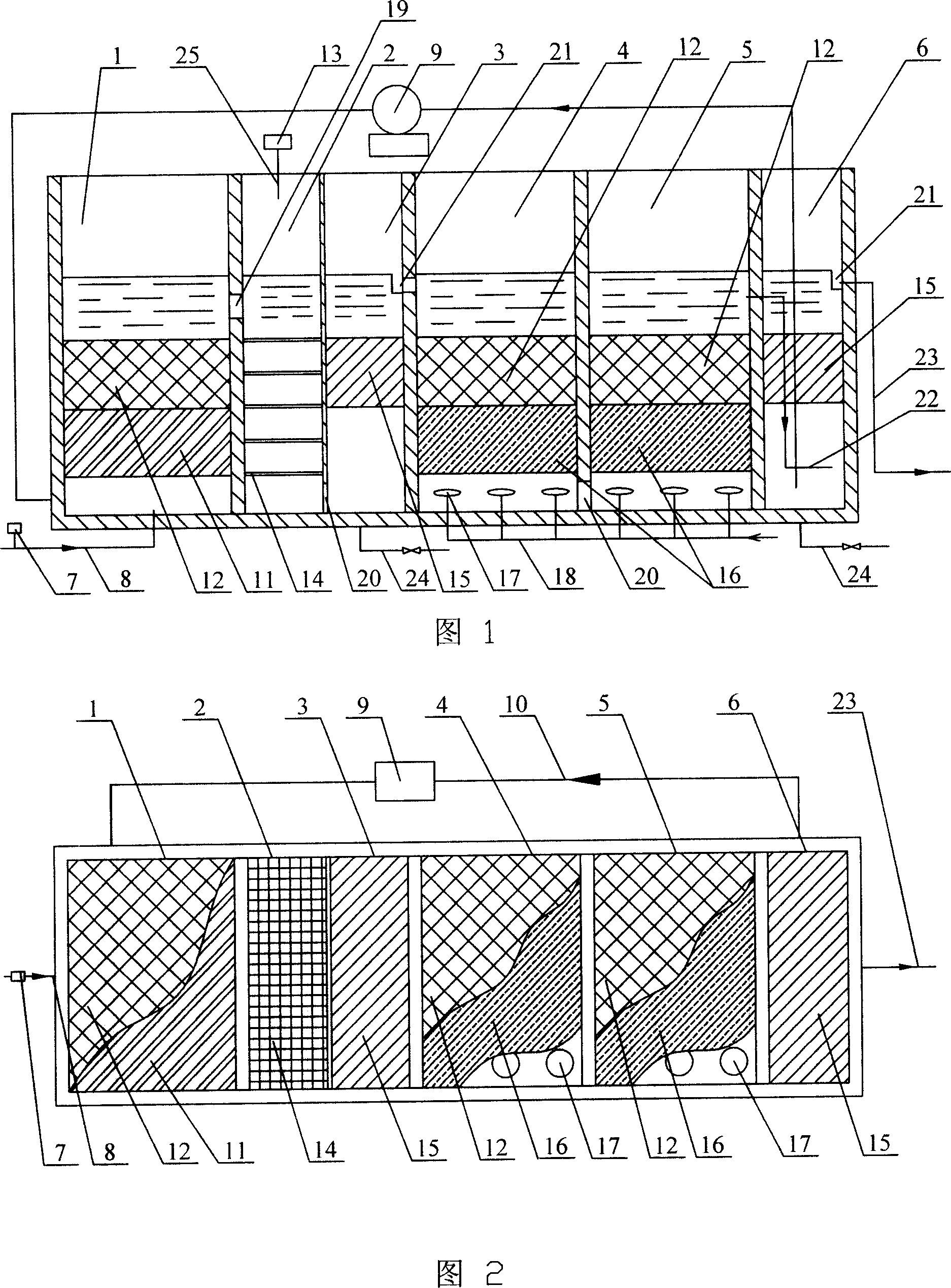
[0027] Specific embodiment one: (referring to Fig. 1 and Fig. 2) the composite micro-electrolysis / biofilm reaction device of the present embodiment is composed of the first micro-electrolysis / biofilm reaction tank 1, the flocculation tank 2, the first sedimentation tank 3, the second micro-electrolysis tank The electrolysis / biofilm reaction tank 4, the third micro-electrolysis / biofilm reaction tank 5 and the second sedimentation tank 6; It is hydraulically connected with the first sedimentation tank 3 through the bottom hole 20, the first sedimentation tank 3 is in hydraulic communication with the second micro-electrolysis / biofilm reaction tank 4 through the sump 21, and the second micro-electrolysis / biofilm reaction tank 4 is connected with the third micro-electrolysis / biofilm reaction tank 4. The electrolysis / biofilm reaction tank 5 is hydraulically connected through the bottom hole 20, the third micro-electrolysis / biofilm reaction tank 5 communicates with the second sediment...

specific Embodiment approach 2

[0028] Specific embodiment two: the difference between this embodiment and specific embodiment one is that the first micro-electrolysis / biofilm reaction tank 1, the second micro-electrolysis / biofilm reaction tank 4 and the third micro-electrolysis / biofilm reaction tank 5 adopt coke , fly ash or slag to replace the activated carbon particles in the activated carbon packing layer 12. Others are the same as in the first embodiment.

specific Embodiment approach 3

[0029] Specific embodiment three: the thickness of the activated carbon packing layer 12 in the first micro-electrolysis / biofilm reaction tank 1 of the present embodiment, the second micro-electrolysis / biofilm reaction tank 4 and the 3rd micro-electrolysis / biofilm reaction tank 5 is 0.1~2m, the activated carbon particle diameter of activated carbon packing layer 12 is 1~5mm; 5-10mm; the thickness of the copper and iron filing layer 16 in the second micro-electrolysis / biofilm reaction tank 4 and the third micro-electrolysis / biofilm reaction tank 5 is 0.1-2m, and the copper and iron filing layer 16 of the copper filings The diameters of copper and iron filings are 5-10mm, and the content ratio of copper filings and iron filings is 1:2-10. Others are the same as in the first embodiment.


PUM

PropertyMeasurementUnit
thicknessaaaaaaaaaa
particle diameteraaaaaaaaaa
diameteraaaaaaaaaa

Abstract

The invention relates to a combined microelectrolytic/biological membrane reactor and the sewage treating method thereof, relating to a sewage treating reaction device and method. And it comprises first microelectrolytic/biological reaction tank, flocculation tank, first settling tank, second microelectrolytic/biological reaction tank, third microelectrolytic/biological reaction tank and second settling tank, where the first microelectrolytic/biological reaction tank holds microbe inoculating iron chips filling layer and activated carbon filling layer. And the invention has advantages of high organic pollutant treating efficiency, sewage denitrification, no electrode passivation, simple process flow, less occupied area, etc.

Description

technical field [0001] The invention relates to a reaction device and method for treating sewage. Background technique [0002] The purification mechanism of micro-electrolysis technology mainly relies on the electrochemical reduction generated by the electrode reaction and the flocculation of Fe ions produced by the electrode. Electrochemical reduction is only suitable for the decomposition mode of some complex organic substances, and cannot achieve the purpose of effective removal of organic pollutants that cannot be electrochemically reduced; the flocculation of Fe ions has obvious removal effects on suspended and colloidal compounds in sewage. However, it has no obvious removal effect on soluble compounds. Therefore, the existing micro-electrolysis technology can achieve high removal efficiency when dealing with sewage from industries such as dyes, printing and dyeing, electroplating, and papermaking. , the defect of unstable reaction operation. [0003] Taking nitro ...

Claims


Application Information

Patent Timeline
Patent Type & Authority Applications(China)
IPC IPC(8): C02F3/02C02F1/461C02F1/52
CPCY02W10/10
Inventor 李欣
Owner HARBIN INST OF TECH
Why Eureka
Try Eureka