
Epoxy resin composition

A technology of epoxy resin and composition, which is applied in printed circuits, electrical components, circuits, etc., can solve problems such as damage to film properties, difficulty in forming thin films, difficulty in thermal conductivity and insulation balance, etc., and achieve low dielectric loss factor, Effect of low dielectric constant

Inactive Publication Date: 2007-04-04
NAMICS CORPORATION
View PDF2 Cites 3 Cited by
  • Summary
  • Abstract
  • Description
  • Claims
  • Application Information

AI Technical Summary

Problems solved by technology

However, there is a problem in these technologies that it is very difficult to process the cured product of the resin into a thin film shape.
[0006] Specifically, the following problems are pointed out: 1) it is difficult to form a uniform film due to the coagulation of the resin composition during the filming operation; 2) air bubbles involved in the filming operation are generated, and needle-like holes are generated on the film; 3. ) Even if it can be made into a thin film, when the raw film is cured under the specified curing conditions, aggregation accompanied by the dissolution of the resin occurs, which also damages the characteristics of the film; 4) Sometimes the raw film has appropriate peelability from the PET film of the support , Compared with adherends, it is difficult to construct as a uniform film
However, such a resin composition has problems in that, on the one hand, its processability is poor, and it is difficult to achieve a desired balance of thermal conductivity and insulation;

Method used

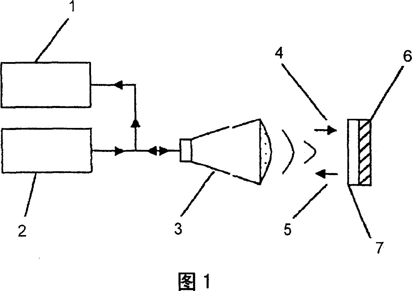
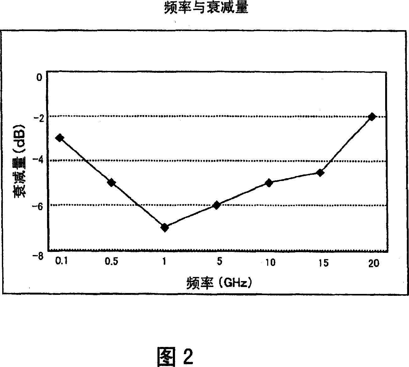

Image

  • Epoxy resin composition
  • Epoxy resin composition
  • Epoxy resin composition

Examples


Embodiment 1~2、 comparative example 1~5

[0089] The varnishes of the resin compositions were prepared in the formulations shown in Table 1. Then, a thin film was formed from the obtained varnish, and tests were performed according to the following evaluations 1 to 9. Table 1 shows the results.

[0090] Evaluation 1 (dielectric characteristics)

[0091] On a film with a release agent (silicone-based release agent, PET film) as a support, it is coated using a doctor blade coater, slot die coater or micro gravure coater so that The cured thickness is 2-90 μm, and an uncured film is obtained after drying.

[0092] Then, it was cured under the conditions of 80°C for 30 minutes, 100°C for 60 minutes, 150°C for 60 minutes, and 180°C for 60 minutes. state, a thin film is obtained. On this cured film, an uncured thin film of the same composition is further laminated and cured by vacuum heating. The obtained film was processed into a width of 1.5 mm, a length of 80 mm, and a thickness of 0.5 mm to prepare a sample.

[009...

Embodiment 3~10、 comparative example 6~7

[0126] A varnish was prepared as an inorganic filler-added resin composition in the formulation shown in Table 2. Then, a thin film was formed from the obtained varnish, and a test was performed according to the above evaluations 1 and 2 to 9 and the following evaluations 10 to 13. The results are shown in Table 2.

[0127] Evaluation 10 (film formability)

[0128] A film of 20 to 200 μm was produced on PET using a slot die coater. Uncured films can be produced with a dry thickness accuracy of ±5%. The results are shown in Table 2.

[0129] Evaluation 11 (winding property of film)

[0130] A 10 m uncured film (thickness 30 μm) was wound on a 37 mm core, and then unrolled, and cracks and the like on the film were observed. The results are shown in Table 2.

[0131] Evaluation 12 (thermal conductivity)

[0132] Using the varnishes of the resin compositions of Examples 6 and 7 to which thermally conductive fillers were added, a cured film with a thickness of 100 μm was obt...


PUM

PropertyMeasurementUnit
peel strengthaaaaaaaaaa
epoxy equivalentaaaaaaaaaa
peel strengthaaaaaaaaaa

Abstract

To provide an epoxy resin composition which can form a cured material having low dielectric constant and low dielectric loss tangent in a radio frequency region, and a film obtained by using the epoxy resin composition. An epoxy resin composition comprising: (A) at least one epoxy resin selected from the group consisting of a novolac epoxy resin having a phenolic skeleton and a biphenyl skeleton, and a bifunctional linear epoxy resin having a weight average molecular weight of 10,000 to 200,000 and having a hydroxyl group; and (B) a modified phenolic novolac having a phenolic hydroxyl group, at least part of which is esterified with a fatty acid.

Description

technical field [0001] The present invention relates to an epoxy resin composition that forms a cured product with a low dielectric loss factor in a high frequency region, and a film obtained by using the epoxy resin composition. In addition, the present invention relates to an epoxy resin composition that forms a cured product imparted with desired electrical and physical properties by adding an inorganic filler, and a film obtained by using the epoxy resin composition. Background technique [0002] In the highly information-based society of recent years, as represented by mobile phones, high-frequency transmission for high-speed and large-capacity information is steadily developing. In order to comply with this, printed wiring boards and module substrates used in electronic equipment such as information terminal equipment must also use materials with low dielectric dissipation factors that reduce transmission loss in the high frequency range. [0003] Currently, epoxy res...

Claims


Application Information

Patent Timeline
Patent Type & Authority Applications(China)
IPC IPC(8): C08G59/62H01L23/14H05K1/03H01L23/498
CPCH01L2924/0002H01L23/49894H05K2201/0358H05K1/0326C08G59/621Y10T428/12569H01L2924/00C08L63/10C08G59/62C08L63/00
Inventor 山田俊昭藤野拓寺木慎吉田真树铃木宪一
Owner NAMICS CORPORATION
Learn More