
Wafer platform mask platform synchronous control system of step-scan photoetching machine

A step-and-scan, synchronous control technology, applied in opto-mechanical equipment, control using feedback, microlithography exposure equipment, etc., can solve the problems of waste, quality decline of finished products, scanning synchronization error exceeding the limit, etc., to achieve fast response speed , reduce synchronization error, improve the effect of precision

Inactive Publication Date: 2007-05-23
INST OF ELECTRICAL ENG CHINESE ACAD OF SCI
View PDF2 Cites 27 Cited by
  • Summary
  • Abstract
  • Description
  • Claims
  • Application Information

AI Technical Summary

Problems solved by technology

However, this patent only detects the "bad field" where the synchronization error exceeds the limit, and does not take any measures to reduce the synchronization error, which may cause the scanning synchronization error of the next subfield to continue to exceed the limit, resulting in a decline in the quality of the finished product and unnecessary waste of

Method used


Image

  • Wafer platform mask platform synchronous control system of step-scan photoetching machine
  • Wafer platform mask platform synchronous control system of step-scan photoetching machine
  • Wafer platform mask platform synchronous control system of step-scan photoetching machine

Examples


Embodiment Construction

[0034] As shown in FIG. 3 , the wafer stage mask stage synchronization control system of the present invention includes four modules: a main control module 13 , a wafer stage control module 12 , a mask stage control module 10 , and a synchronization control module 11 . The main control module 13 includes a main control CPU card 101, whose function is to send scanning instructions to each module and specify parameters such as scanning synchronization error, scanning speed and acceleration. The wafer stage control module 12 includes: a motion control card 102a, and a position data acquisition card 103a. The former is responsible for adjusting the motion trajectory, speed and acceleration of the wafer stage, and the latter is responsible for collecting the position information of the wafer stage in real time and feeding it back to the motion control card 102a. The mask stage control module 10 includes: a motion control card 102b, and a position data acquisition card 103b. The fo...


PUM


Abstract

A step-and-scan optical engraver wafer station mask station control system, its characteristics are: it comprises the main control module [13], the wafer station control module [12], the masking station control module [10] and the synchronization control module [11]. The invention uses the synchronous control with disturbance controller to reduce the effect of the movement precision and stability of disturbance to the wafer station and masking station, and it introduces the synchronization control compensation device to reduce the synchronization error, and finally improve the optical engraver accuracy. The invention can not only realize step-and-scan movement required during the scanning exposure process, but also improve the machinery precision and stability. The invention is applicable to optical scan projection optical engraver, and extreme ultraviolet scanning exposure machine, and the synchronous control of other micro-processing equipment.

Description

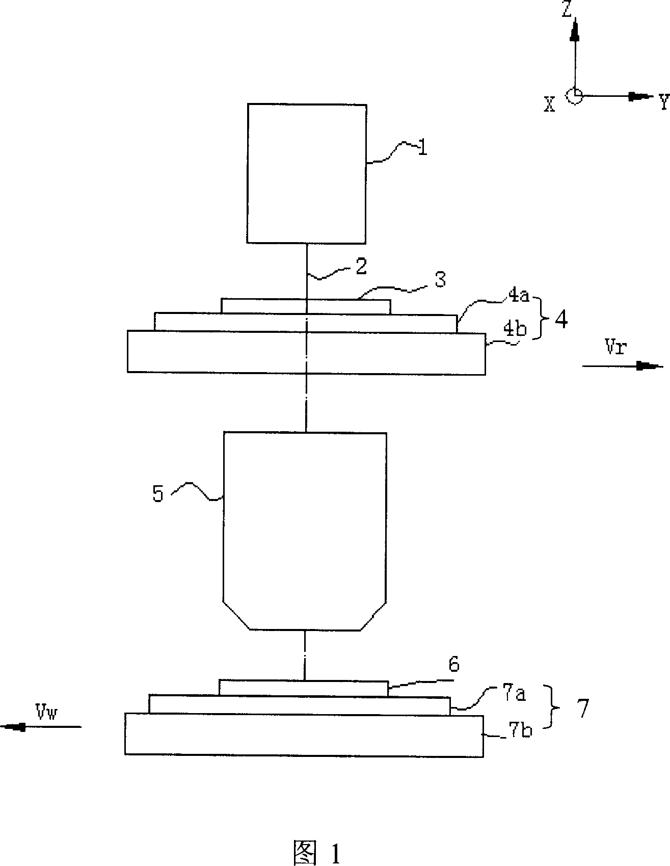
technical field [0001] The invention relates to a synchronous control system of a step-and-scan lithography machine, in particular to a synchronous control system for a wafer stage mask stage of a step-scan lithography machine. Background technique [0002] Step-and-scan projection lithography technology is a cutting-edge technology in IC lithography processing. It uses the synchronous movement of the mask stage and wafer stage to project the graphics on the mask onto the resist-coated wafer through the miniature optical system. , and then after shaping, developing and other processes, the graphics with reduced magnification are finally copied on the wafer. Scanning exposure is different from one-time full exposure. It uses the uniform linear scanning of the conventional narrow slit image field to realize continuous moving exposure in the large chip size image field. The projection error and aberration can be reduced due to the image field equalization; in addition The cont...

Claims


Application Information

Patent Timeline
IPC IPC(8): G03F7/20G05D3/12G03F7/22G03F9/00
Inventor 朱涛李艳秋
Owner INST OF ELECTRICAL ENG CHINESE ACAD OF SCI
Learn More