
Method and apparatus for processing of detector signals

A detector and photoelectric detector technology, which is applied in measurement devices, instruments for radiological diagnosis, signal transmission systems, etc., to achieve the effect of reducing technical expenses and numbers

Inactive Publication Date: 2007-05-30
SIEMENS AG
View PDF1 Cites 16 Cited by
  • Summary
  • Abstract
  • Description
  • Claims
  • Application Information

AI Technical Summary

Problems solved by technology

However, since the method does not necessarily work in high magnetic fields like PET cameras in MR magnets, complex signal processing methods can be used here

Method used


Image

  • Method and apparatus for processing of detector signals
  • Method and apparatus for processing of detector signals
  • Method and apparatus for processing of detector signals

Examples


Embodiment Construction

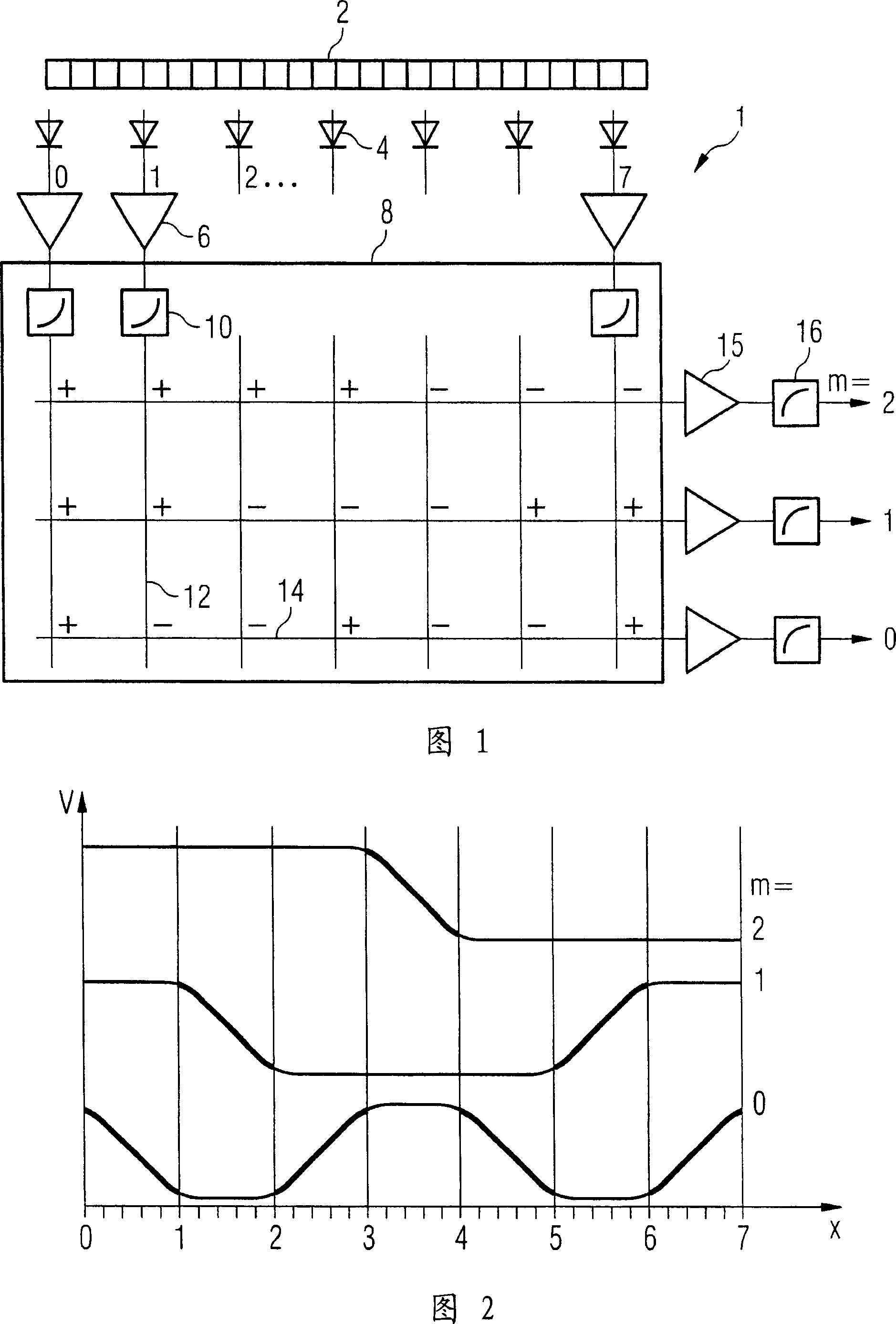
[0050] Fig. 1 schematically shows the structure of a gamma camera 1 with signal processing according to an embodiment of the present invention. The scintillation crystals 2 of the detector are shown here as a one-dimensional array for clarity, although typically they occur in two-dimensional arrangements. When a gamma quantum is incident on the crystal 2 a flash of light will be produced which is detected by one or more photodetectors 4 . In this illustrative example, N=8 detectors are shown, which are, for example, avalanche photodiodes. The signals generated by these detectors 4 are amplified by amplifiers 6 and transmitted on output lines 14 in a weighting matrix 8 according to one embodiment of the invention.

[0051] Preferably, each detector signal is amplified with a non-linear characteristic curve by means of an amplifier or diode 10 in order to suppress the noise level of the inactive detector channel. The detector signals present on the input lines 12 are then tran...


PUM


Abstract

A method and an apparatus are disclosed for processing of detector signals, for example in nuclear-medical imaging. In at least one disclosed embodiment, the signals from N photodetectors are transmitted to a total of approximately M=ld(N) output lines, with the signals from the photodetectors each being weighted with +1 or -1 for the addition onto an output line.

Description

technical field [0001] The invention relates to a method and a device for processing detector signals in nuclear medicine imaging, which can be used for processing signals of photodetectors of PET cameras arranged in MR magnets. Background technique [0002] The purpose of nuclear medicine imaging is to visualize physiological and biochemical processes inside the body. Here, the patient is administered a radionuclide-bearing tracer, which distributes in the body so that it emits radioactive radiation. The radiation is measured using a camera including appropriate detectors, thereby determining the distribution of the tracer in the body. In positron emission tomography (PET), positron emitters are used as tracers, emitting positrons that break down into two opposing gamma quanta within the body. In contrast, in SPECT (Single Photon Emission Computed Tomography, Single Photon Emission Computed Tomography) imaging, gamma emitters are used as radionuclides. In both cases, the...

Claims


Application Information

Patent Timeline
IPC IPC(8): G08C19/16G08C19/00G01T1/161G01T1/164G01T1/20G01T1/24A61M36/00A61B6/00
CPCG01T1/1644G01T1/1647A61B6/037
Inventor 马库斯·维斯特
Owner SIEMENS AG
Features
  • Generate Ideas
  • Intellectual Property
  • Life Sciences
  • Materials
  • Tech Scout
  • Unparalleled Data Quality
  • Higher Quality Content
  • 60% Fewer Hallucinations
Learn More