Solid electrolyte fuel cell
一种固体电解质、固体电解质层的技术,应用在固体电解质燃料电池、燃料电池、燃料电池的零部件等方向,能够解决没有提高、电功率输出提高、三相界面面积减小等问题,达到面积增大、热膨胀系数差异最小化的效果
- Summary
- Abstract
- Description
- Claims
- Application Information
AI Technical Summary
Problems solved by technology
Method used
Image

Examples
Embodiment 1
[0062] (1) Preparation of solid electrolyte fuel cells
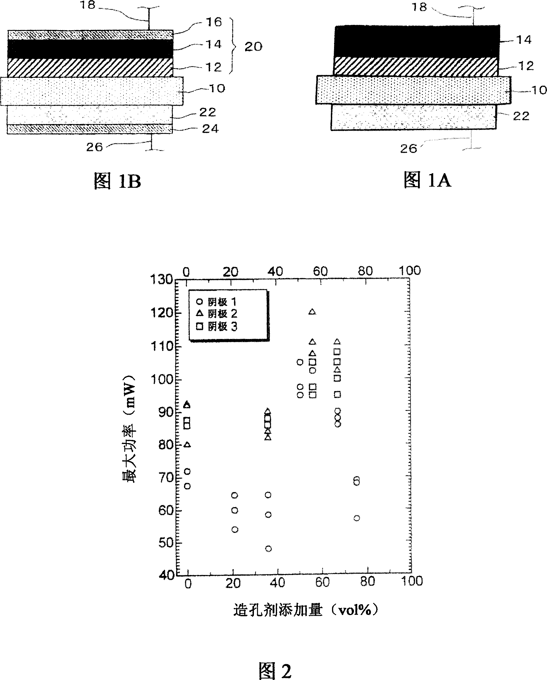
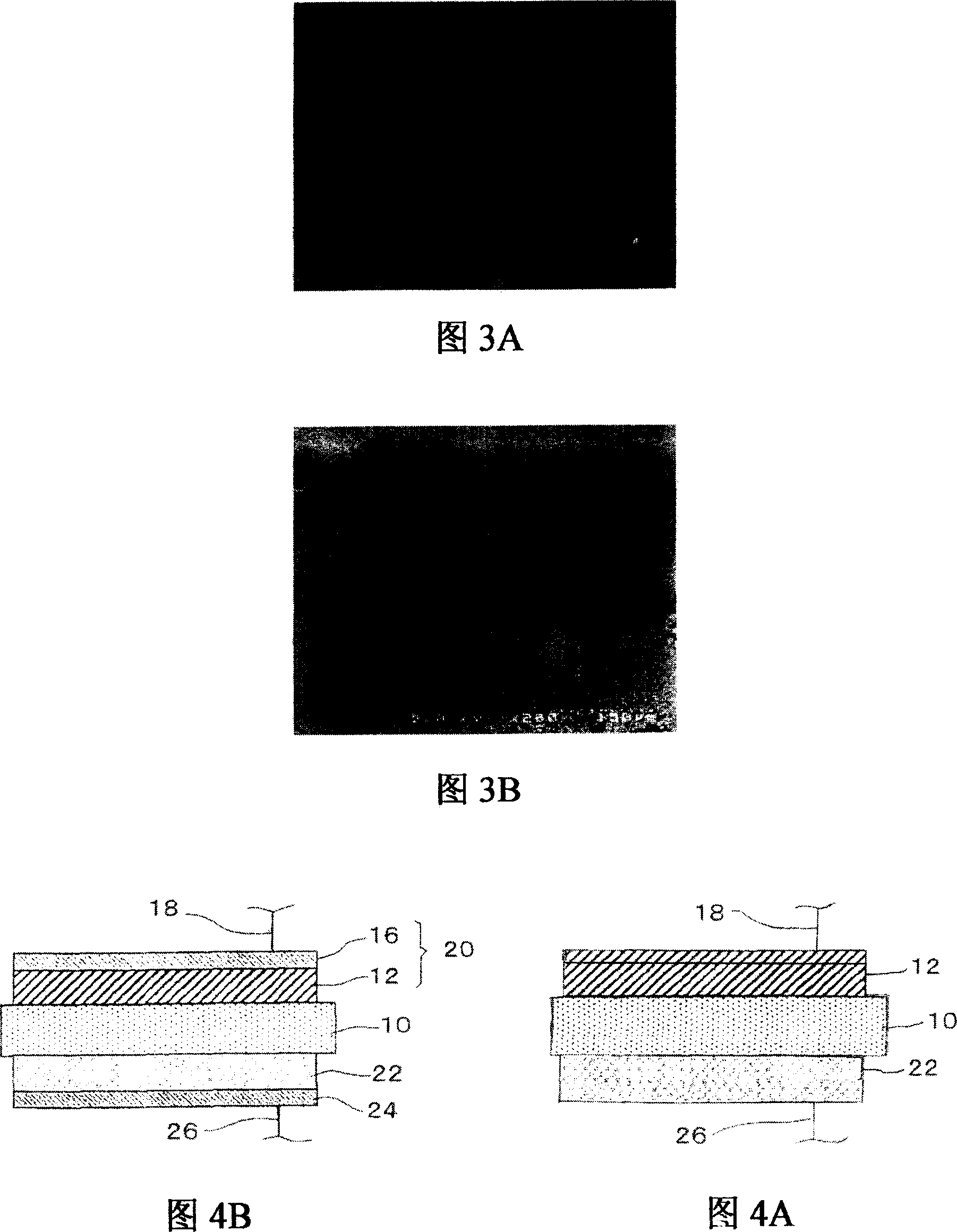
[0063] Use Sm with a thickness of 180μm and a diameter of φ15mm 0.2 Ce 0.8 o 1.9 A (samarium oxide-doped ceria: SDC) ceramic substrate is used as the solid electrolyte layer 10, wherein the ceramic substrate is obtained by forming a green sheet by a doctor blade method (a tape casting method), and the green sheet is formed from the Plates A circular plate was punched out, which was then fired at 1300°C.
[0064] 20% by weight of SDC, 5% by weight of Rh 2 o 3 (rhodium oxide) and 8 mol% Li-NiO 2 Mix to obtain the anode layer paste, and then print the paste as a sheet-like material constituting the anode layer 22 by sheet-printing (sheet-printed) (distribution area: 1.3 cm 2 ) to one surface (area: 1.8cm) of the ceramic substrate as the solid electrolyte layer 10 2 )superior.
[0065] In addition, from Sm containing 50% by weight SDC 0.5 Sr 0.5 CoO 3 (Samarium strontium cobaltate: SSC) to make a dense layer paste...
Embodiment 2
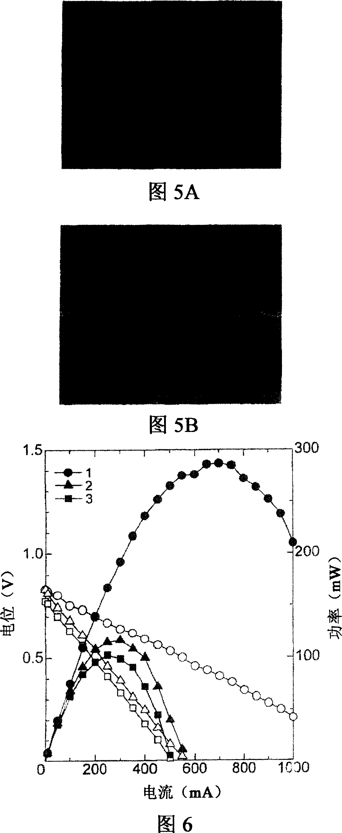
[0080] The solid electrolyte fuel cells prepared in Example 1 and Comparative Examples 1 and 2 were tested for power generation performance by applying the premixed flame of the burner to the surface of the anode layer 22 side, wherein the burner Butane gas with a concentration of 6.5% was used as fuel. The test results are shown in Figure 6.
[0081] In FIG. 6 , solid marks represent electric power [power (mW)] corresponding to current, and open marks represent electric potential [potential (V)] corresponding to current. In Fig. 6, No. 1 represents the test result of the solid electrolyte fuel cell of Example 1 (comprising a cathode layer 20 composed of a dense layer 12, a porous layer 14 and a mesh metal 16), and No. 2 represents the solid electrolyte of Comparative Example 1 The test result of the fuel cell (comprising only the cathode layer 20 composed of dense layer 12 and mesh metal 16), No. 3 represents the solid electrolyte fuel cell of comparative example 2 (comprisi...
Embodiment 3
[0085] By applying the premixed flame of the burner to the surface of the anode layer 22 side, the solid electrolyte fuel cells prepared in Example 1 and Comparative Example 2 were respectively tested for power generation performance, wherein the burner used a concentration of 6.5% butane gas as fuel. Then, the two solid electrolyte fuel cells are separated from the flame sufficiently so that they can be completely cooled to room temperature, and then the operation of applying the premixed flame of the burner to the surface on the anode layer 22 side is repeated 5 times so as to pass heat Impact tests test them for performance degradation. The test results are shown in Figure 7.
[0086] FIG. 7A is a graph of the power generation performance of the solid electrolyte fuel cell prepared in Example 1. FIG. Even after the solid electrolyte fuel cell of Example 1 was subjected to 5 thermal shocks, it was seen that its power generation performance deteriorated little.
[0087] On...
PUM
| Property | Measurement | Unit |
|---|---|---|
| diameter | aaaaa | aaaaa |
| diameter | aaaaa | aaaaa |
Abstract
Description
Claims
Application Information
 - R&D
- Intellectual Property
- Life Sciences
- Materials
- Tech Scout
- Unparalleled Data Quality
- Higher Quality Content
- 60% Fewer Hallucinations
Browse by: Latest US Patents, China's latest patents, Technical Efficacy Thesaurus, Application Domain, Technology Topic, Popular Technical Reports.
© 2025 PatSnap. All rights reserved.Legal|Privacy policy|Modern Slavery Act Transparency Statement|Sitemap|About US| Contact US: help@patsnap.com