
Dielectric ceramic composition and electronic device

一种陶瓷组合物、电介质的技术,应用在固定电容器电介质、固定电容的零部件、陶瓷等方向,能够解决不能显示出温度特性等问题,达到容量时效特性良好、可靠性好、低成本化的效果

Active Publication Date: 2007-06-13
TDK CORPARATION
View PDF11 Cites 5 Cited by
  • Summary
  • Abstract
  • Description
  • Claims
  • Application Information

AI Technical Summary

Problems solved by technology

However, in the technique of Patent Document 12, since Ca is completely dissolved in barium titanate, although the dielectric constant is high, good temperature characteristics cannot be exhibited.

Method used


Image

  • Dielectric ceramic composition and electronic device
  • Dielectric ceramic composition and electronic device
  • Dielectric ceramic composition and electronic device

Examples


Embodiment 1

[0221] Manufacture of Dielectric Raw Materials

[0222] First, barium titanate raw materials and auxiliary component raw materials are prepared. BaTiO with an average particle size of 0.25 μm is used as the barium titanate raw material 3 (hereinafter referred to as BT). MgO, MnO, and V with an average particle size of 0.01 to 0.1 μm are used as subcomponent raw materials 2 o 5 , (Ba 0.6 Ca 0.4 ) SiO 3 (hereinafter referred to as BCG), Y 2 o 3 , Yb 2 o 3 , and CaZrO as Ca raw material 3 . BCG is manufactured as follows: BaCO 3 , CaCO 3 , SiO 2 Wet mixed for 16 hours, dried, sintered in air at 1150°C, and then wet pulverized with a ball mill for 100 hours. CaZrO 3 Manufactured as follows: Wet mixing CaCO with a ball mill 3 , ZrO 3 After 16 hours of drying, it was sintered in the air at 1150°C, and wet pulverized by a ball mill for 24 hours.

[0223] Next, these raw materials are weighed, and the composition after sintering is 0.9 mol of MgO, 0.37 mol of MnO...

Embodiment 2

[0261] In addition to using CaCO as Ca raw material 3 , Ca-Y-Si-O, and the sample 4 (CaZrO 3 ) Similarly, the same evaluation as in Example 1 was performed. The results are shown in Table 2.

[0262] Table 2

[0263] sample

Number

Ca raw material

calcined

sintering

Grain

Capacitor sample

IR temperature

dependency

maintain temperature

(℃)

time

(h)

maintain temperature

(℃)

time

(h)

*Average depth T of Ca diffusion region

(%)

*Average depth of Mg diffusion zone

(%)

at 150°C

Capacity change rate %)

×8R

Dielectric

constant

type

add method

11

Example

CaCO 2

Solid Phase

700

5

1240

6

30

16.4

-8.9

1350

-1.87

4

Example

CaZrO 3

Solid Phase

700

5

1240

6

23

16.4

...

Embodiment 3

[0268] The same evaluation as in Example 1 was performed in the same manner as in Sample 4 (6 hours) in Example 1 except that the sintering time was changed to 0.5 hours, 2 hours, 15 hours, and 30 hours. The results are shown in Table 3.

[0269] table 3

[0270] sample

Number

Ca raw material

calcined

sintering

Grain

Capacitor sample

IR temperature

dependency

maintain temperature

(℃)

time

(h)

maintain temperature

(℃)

time

(h)

*Average depth T of Ca diffusion region

(%)

*Average depth of Mg diffusion zone

(%)

at 150°C

Capacity change rate (%)

×8R

Dielectric

constant

type

add method

21

comparative example

CaZrO 2

Solid Phase

700

5

1240

30

43.1

18.1

-20.1

×

1326

-2.46

22

Example

CaZrO 3

Solid Phase

700...


PUM

PropertyMeasurementUnit
particle diameteraaaaaaaaaa

Abstract

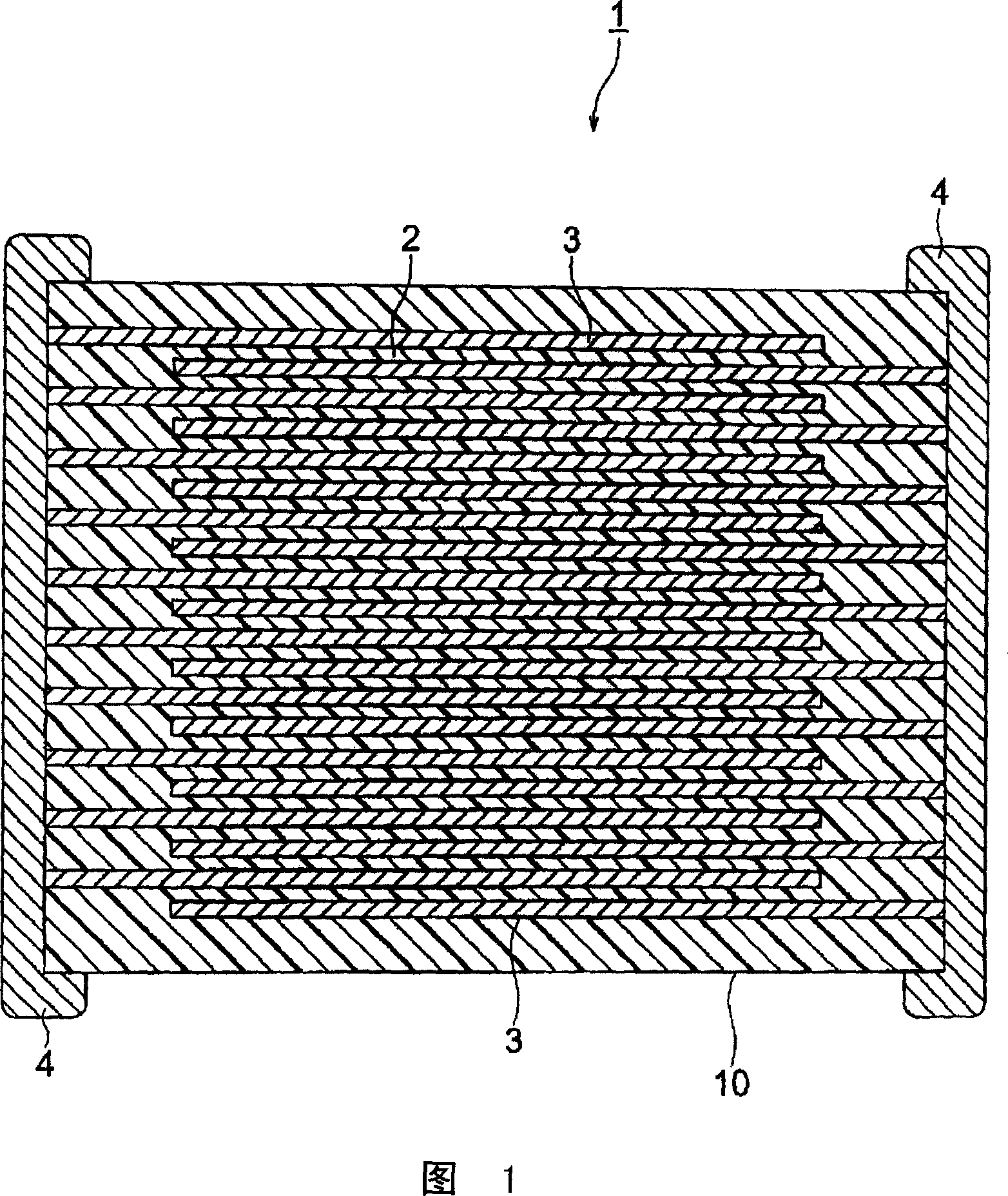
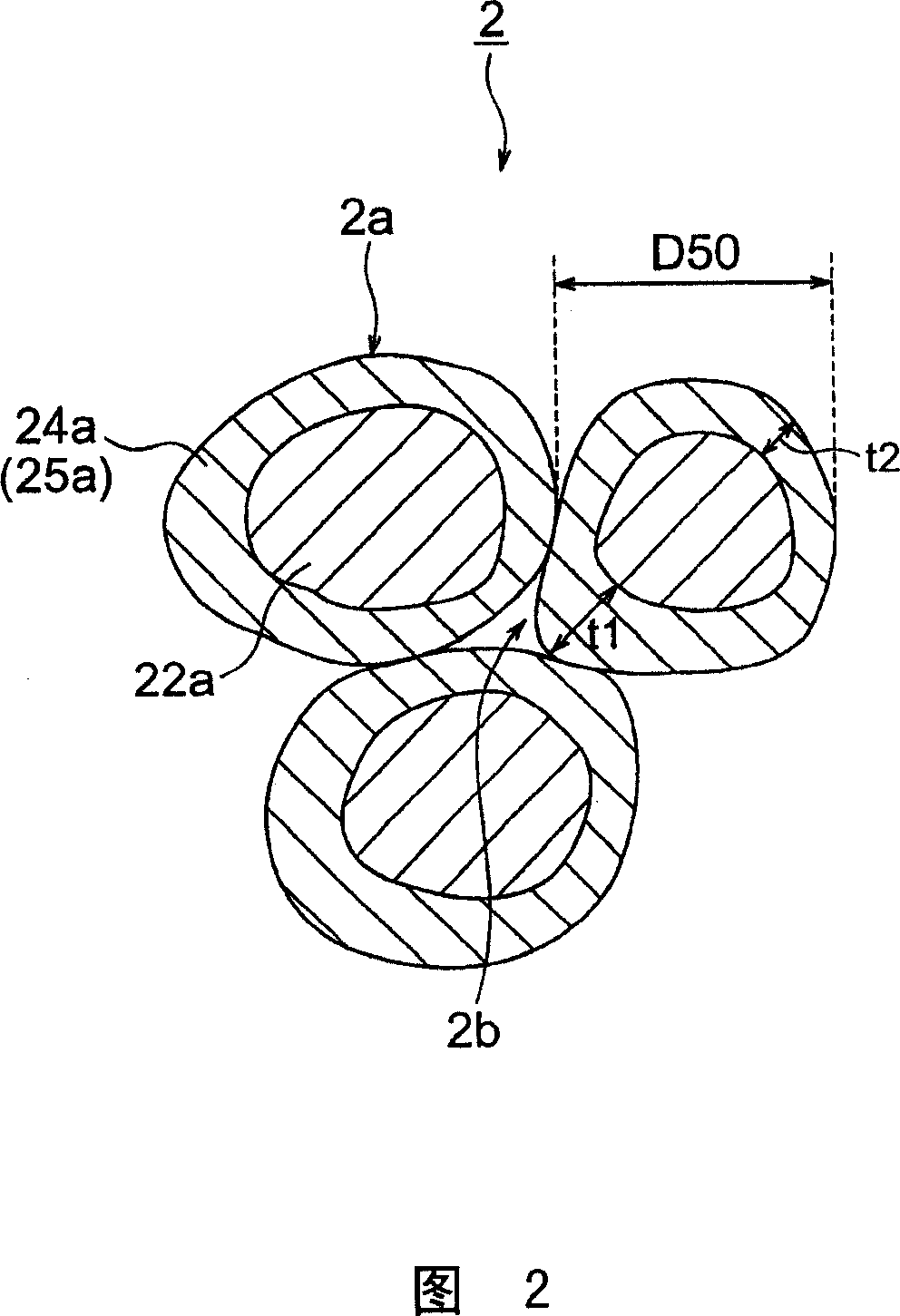
An object of the invention is to provide a multilayer ceramic capacitor having high dielectric constant, good temperature characteristic, and an improved IR temperature dependency. According to the present invention, a capacitor device body 10, wherein dielectric layers 2 comprising dielectric ceramic composition and internal electrode layers 3 are alternately laminated, characterized in that said dielectric ceramic composition comprises a plural number of crystal particles 2a wherein said crystal particles 2a form Ca dispersing area 25a wherein at least said Ca is dispersed from the surface to inside of crystal particles, and when considering crystal particles 2a having an average particle diameter of D50, an average depth T of said Ca dispersing area is controlled within a range of 10 to 30% with respect to the average particle diameter of D50, is provided.

Description

technical field [0001] The present invention relates to a dielectric ceramic composition having reduction resistance, and electronic components such as a multilayer ceramic capacitor using the dielectric ceramic composition. Background technique [0002] In multilayer ceramic capacitors used as electronic components, in addition to high dielectric constant, long life of insulation resistance IR, good DC bias characteristics (less change in dielectric constant over time), good temperature characteristics are also required, especially , According to the application, the temperature characteristics are required to be flat under severe conditions. In recent years, ceramic capacitors have been used in various electronic devices such as engine electronic control units (ECUs), crank angle sensors, and anti-lock braking system (ABS) modules mounted in the engine compartment of automobiles. Since these electronic devices are used to stably perform engine control, drive control, and ...

Claims


Application Information

Patent Timeline
Patent Type & Authority Applications(China)
IPC IPC(8): C04B35/495C04B35/468H01G4/12H01G4/30
CPCC04B2235/6025C04B35/62807C04B35/62645C04B2235/785Y10T428/2996Y10T428/2995C04B2235/6582C04B35/62685C04B35/62805C04B2235/6588C04B2235/3427H01G4/1227C04B2235/5445C04B2235/3217C04B2235/3258C04B2235/3205Y10T428/2993C04B2235/3224Y10T428/2982C04B2235/3239C04B2235/3213C04B35/6281C04B2235/3244H01L41/1871C04B2235/3293C04B2235/3225C04B35/62815C04B2235/3206C04B2235/3436C04B2235/3208C04B2235/3256C04B2235/3262C04B2235/663C04B2235/3409C04B2235/3418C04B2235/3454C04B35/64C04B2237/405B32B2311/22C04B2237/346C04B2235/3215C04B2235/3203C04B35/62897C04B35/4682C04B35/62823C04B2235/72C04B2235/656C04B35/628Y02T10/7022Y10T428/2991C04B2235/3249H01B3/12Y02T10/70H10N30/8536C04B35/468C04B35/46C04B35/462
Inventor 伊东和重佐藤阳
Owner TDK CORPARATION
Learn More